Autonomous address translation in graphic subsystem

a graphic subsystem and autonomous technology, applied in the field of computer graphics rendering systems and methods, can solve the problems of still large amount of data manipulation to be done, rendering is a computationally intensive operation, and adding polygons necessitates paying the price of having to manipulate more geometry

Inactive Publication Date: 2006-05-23
ZIILABS INC LTD A ORGANIZED UNDER THE LAWS OF BERMUDA +2
View PDF17 Cites 16 Cited by
  • Summary
  • Abstract
  • Description
  • Claims
  • Application Information

AI Technical Summary

Benefits of technology

[0058]Note that the preferred controller doesn't interfere with the fetch to host memory—only the fetch to CARD memory. No

Problems solved by technology

However, even after these transformations and extensive calculations have been done, there is still a large amount of data manipulation to be done: the correct values for EACH PIXEL of the transformed polygons must be derived from the two-dimensional representation.
The most challenging 3D graphics applications are dynamic rather than static.
Since rendering is a computationally intensive operation, numerous designs have offloaded it from the main CPU.
However, adding polygons necessitates paying the price of having to manipulate more geometry.
Due to the extremely high data rates required at the end of the rendering pipeline, many features of computer architecture take on new complexities in the context of computer graphics (and especially in the area of texture management).
SRAMs are much more expensive (per bit) than DRAMs, and DRAMs are much more expensive (per bit) than disk memory.
When the central processing unit (CPU) executes software, it will often have to read or write to an arbitrary (unpredictable) address.
However, the needs and impact of virtual memory operation are largely irrelevant to the disclosed innovations, and will be largely ignored in the present application.)
This causes “wait states,” which are undesirable.
The net effective speed of a large DRAM memory can be increased by using bank organization and/or page mode accesses; but such features can still provide only a limited speed improvement, and net effective speed of a large DRAM memory (as seen by the processor) will still typically be much slower than that of the processor.
However, low-priced DRAM memories typically have access times of 50 ns or more.
This will normally be organized with various architectural tricks to hasten average access time, but only a limited amount of improvement can be readily achieved by such methods.
Some of these technologies have a cost per bit which is nearly as low as DRAM, but these technologies tend to have access times which are slower than DRAM.
Moreover, since these are read-only or read-mostly memories, they are not suited for general-purpose random-access memory.)
The risk in

Method used


Image

  • Autonomous address translation in graphic subsystem
  • Autonomous address translation in graphic subsystem
  • Autonomous address translation in graphic subsystem

Examples


Embodiment Construction

[0080]The numerous innovative teachings of the present application will be described with particular reference to the presently preferred embodiment (by way of example, and not of limitation).

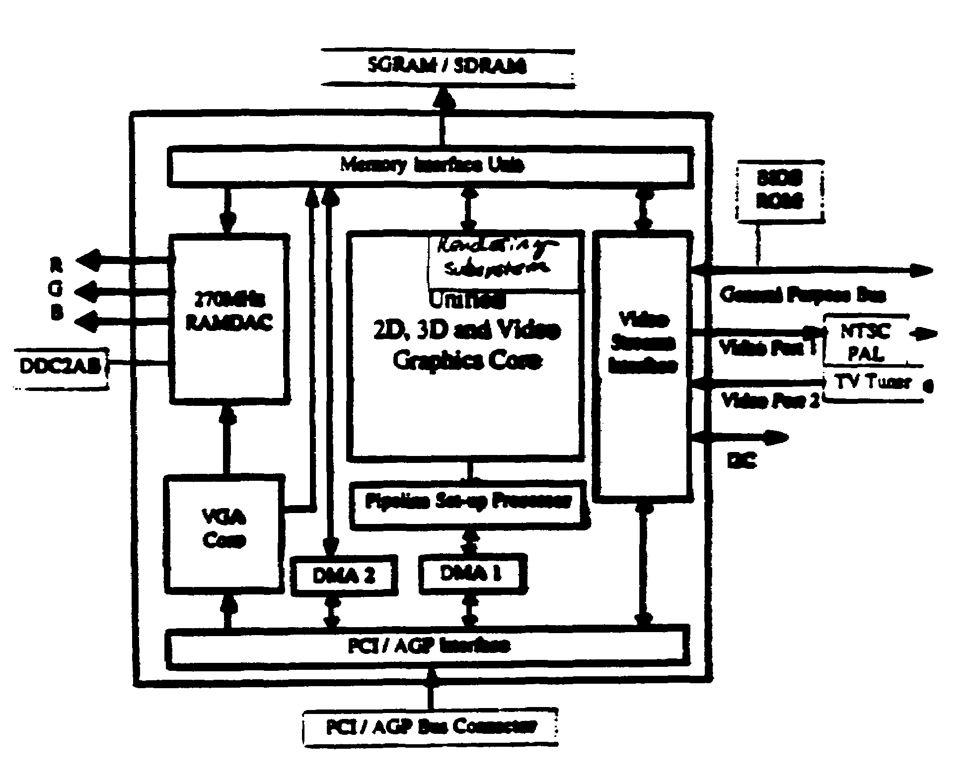
[0081]The following pages give details of a sample embodiment of the preferred rendering accelerator chip (referred to as “P3” in the following document, although not all details may apply to every chip revision marketed as P3). Particular attention will be paid to the Texture Read Unit of this chip, where many of the disclosed inventions are implemented. Commonly-owned U.S. application Ser. Nos. 09 / 322,828, 09 / 280,250, and 09 / 266,052 provide various other details of the contexts within which the claimed inventions are most preferably implemented, and are all incorporated herein by reference. The present application is one of nine applications filed simultaneously, which are all contemplated to be implemented together in a common system. The other applications are Ser. Nos. 09 / 591,533, 09,591,5...


PUM


Abstract

A texture caching controller, located on the graphics card, handles address logical-to-physical translation for texture addresses which are not downloaded to level-1 memory due to low use or dynamically changing values. This offloads texture memory management duties from the host.

Description

[0001]This application claims benefit of provisional applications 60 / 138,350 filed on Jun. 9, 1999, 60 / 138,248 filed on Jun. 9, 1999, and 60 / 143,825 filed on Jul. 13, 1999.BACKGROUND AND SUMMARY OF THE INVENTION[0002]The present application relates to computer graphics rendering systems and methods, and particularly to handling of texture data used by rendering accelerators for 3D graphics.Background: 3D Computer Graphics[0003]One of the driving features in the performance of most single-user computers is computer graphics. This is particularly important in computer games and workstations, but is generally very important across the personal computer market.[0004]For some years the most critical area of graphics development has been in three-dimensional (“3D”) graphics. The peculiar demands of 3D graphics are driven by the need to present a realistic view, on a computer monitor, of a three-dimensional scene. The pattern written onto the two-dimensional screen must therefore be derive...

Claims


Application Information

Patent Timeline
IPC IPC(8): G06T11/40
CPCG06T1/60G06T15/04G06T2200/28
Inventor BALDWIN, DAVID ROBERT
Owner ZIILABS INC LTD A ORGANIZED UNDER THE LAWS OF BERMUDA
Why Eureka
Try Eureka