Multiple simultaneous bin sizes

a bin size and bin size technology, applied in the field of computer graphics, can solve the problems of large data manipulation to be done, large memory bandwidth, and large complexity of opaque depth, and achieve the effect of reducing opaque depth complexity and saving cycles

Active Publication Date: 2016-05-24
MEDIATEK INC
View PDF4 Cites 8 Cited by
  • Summary
  • Abstract
  • Description
  • Claims
  • Application Information

AI Technical Summary

Benefits of technology

[0011]There are different ways to add complexity to a 3D scene. Creating more and more detailed models, consisting of a greater number of polygons, is one way to add visual interest to a scene. However, adding polygons necessitates paying the price of having to manipulate more geometry. 3D systems have what is known as a “polygon budget,” an approximate number of polygons that can be manipulated without unacceptable performance degradation. In general, fewer polygons yield higher frame rates.
[0017]A tiled, binning, chunking, or bucket rendering architecture is where the primitives are sorted into screen regions before they are rendered. This architecture allows all the primitives within a screen region to be rendered together to exploit the higher locality of reference to the z and color buffers, thereby allowing more efficient memory usage typically by using only on-chip memory. This also enables other whole-scene rendering opportunities such as deferred-rendering, order-independent transparency, and new types of antialiasing. In the present application, “transparent” is used generally to designate anything with alpha <1.
[0023]The application can submit the transparent primitives multiple times with a dual depth test to render the transparent surfaces one layer at a time. A layer is the set of farthest transparent primitives (or parts there of) that are in front of the nearest opaque primitives. After each layer is rendered, it is incorporated into the opaque primitives for the next pass. Subsequent layers move closer to the eye position. This technique is called depth peeling. Alternatively, it can be implemented with subsequent layers moving farther away from the eye; however, this requires a triple depth test and is more expensive to render, but has the advantage of terminating early once a certain number of layers has been rendered (extra layers add very little to the fidelity of the image).
[0027]Less FSAA work. During the first pass of the deferred rendering operation, the location of edges (geometric and inferred due to penetrating faces) can be ascertained, and only those sub-tiles holding edges need to have the multi-sample depth values calculated and the color replicated to the covered sample points. This saves cycles to update the multi-sample buffers and any program cost for alpha-blending.
[0032]In the present inventions, the conflicting requirements between the database-building and traversal (i.e. display) phases are resolved by allowing the database bin size to be different from the display bin size. The database bin size is some multiple of the bin display bin size (now call a sub-bin), and when there are multiple sub-bins in a bin, each bin is traversed multiple times for display, and the rasterizer discards primitives outside of the current sub-bin. This allows a trade off between memory bandwidth consumed for database building and bandwidth consumed for display, particularly when the display traversal is done multiple of times.
[0033]In addition to the above-listed advantages, the disclosed innovations, in various embodiments, also provide one or more of at least the following advantages:

Problems solved by technology

However, even after these transformations and extensive calculations have been done, there is still a large amount of data manipulation to be done: the correct values for EACH PIXEL of the transformed polygons must be derived from the two-dimensional representation.
The most challenging 3D graphics applications are dynamic rather than static.
However, adding polygons necessitates paying the price of having to manipulate more geometry.
Achieving an adequately high rate of texturing and fill operations requires a very large memory bandwidth.
There may be no correct rendering order when transparent primitives are cyclically interleaved or penetrated, and in these cases, the application would need to clip the primitives against each other to generate a definitive order.
Alternatively, it can be implemented with subsequent layers moving farther away from the eye; however, this requires a triple depth test and is more expensive to render, but has the advantage of terminating early once a certain number of layers has been rendered (extra layers add very little to the fidelity of the image).
This is similar to accumulation buffering at the application level but occurs without any application involvement (motion blur and depth of field effects cannot be done).
Note that the semantics of OpenGL can make this hard to use.

Method used


Image

  • Multiple simultaneous bin sizes
  • Multiple simultaneous bin sizes
  • Multiple simultaneous bin sizes

Examples


Embodiment Construction

[0055]The numerous innovative teachings of the present application will be described with particular reference to the presently preferred embodiment (by way of example, and not of limitation).

[0056]Multiple Simultaneous Bin Sizes

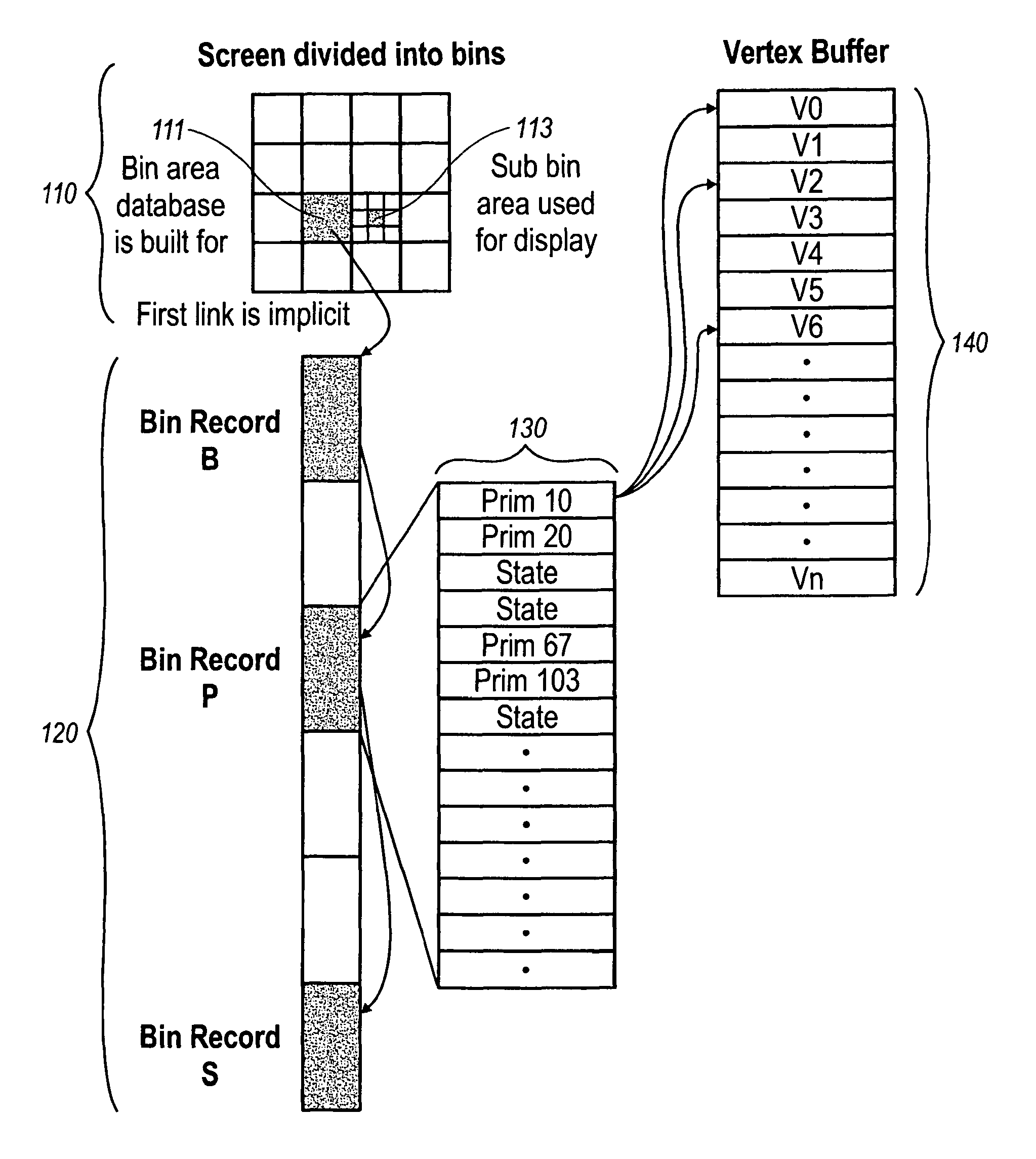
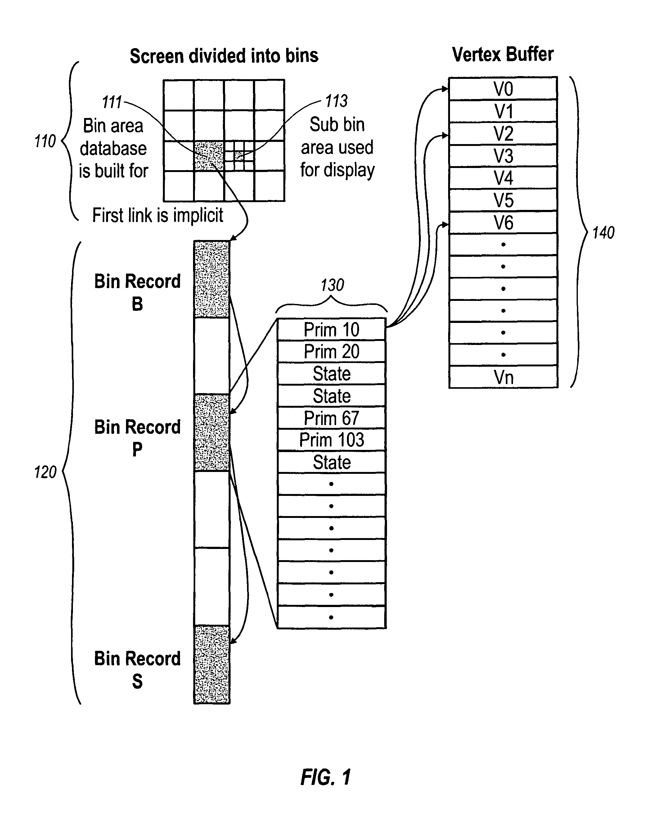
[0057]The database-building and traversal (i.e. display) phases have conflicting requirements, at least within the bounds of current technology:

[0058]For efficient database building, the bin size should be as large as possible so as to minimize the number of bins a primitive can overlap. Typical screen sizes are 1280×1024 so a single bin this size would be ideal from a database-building perspective.

[0059]For efficient display, the z and color buffers for a bin must fit in on-chip memory (typically a cache) as the whole purpose is to save external memory bandwidth. The typical on-chip memory budget may be sufficient to hold 128×64 pixels, but antialiasing can drop down to 32×32 pixels as each pixel now has to hold multiple z and color samples. This translates...


PUM


Abstract

Conflicts between the database-building and traversal phases are resolved by allowing the database bin size to be different from the display bin size. The database bin size is some multiple of the bin display bin size, and when there are multiple display bins in a database bin, each database bin is traversed multiple times for display, and the rasterizer discards primitives outside of the current display bin. This allows a trade off between memory bandwidth consumed for database building and bandwidth consumed for display, particularly when the display traversal is done multiple of times.

Description

CROSS-REFERENCE TO RELATED APPLICATION[0001]This application is a continuation of U.S. patent application Ser. No. 10 / 903,671, filed Jul. 30, 2004 and entitled, “MULTIPLE SIMULTANEOUS BIN SIZES” which claims priority from U.S. Provisional Application 60 / 533,813 filed Dec. 31, 2003, the entirety of which are incorporated by reference for all purposes.FIELD OF THE INVENTION[0002]The present inventions relate to computer graphics and, more particularly, to a computer graphics rendering architecture that utilizes multiple simultaneous bin sizes.BACKGROUND AND SUMMARY OF THE INVENTION[0003]Background: 3D Computer Graphics[0004]One of the driving features in the performance of most single-user computers is computer graphics. This is particularly important in computer games and workstations, but is generally very important across the personal computer market.[0005]For some years, the most critical area of graphics development has been in three-dimensional (“3D”) graphics. The peculiar dema...

Claims


Application Information

Patent Timeline
Patent Type & Authority Patents(United States)
IPC IPC(8): G06T11/40G06T1/60G09G5/36G06T17/10G06T15/04G06T15/00G06T1/20G06T17/20
CPCG06T17/10G06T15/04G06T1/60G06T15/005G06T11/40G06T17/20G06T1/20G09G5/36
Inventor BALDWIN, DAVID R.
Owner MEDIATEK INC
Why Eureka
Try Eureka