
Material with spectrally selective reflection

a technology of selective reflection and material, applied in the direction of mirrors, instruments, spectral modifiers, etc., can solve the problems of superfluous production of fully dielectric layer systems, unsuitable laser projection screens, and significant higher production costs of five-layer systems than the production of three-layer systems. achieve cost-effective production, high refraction index, and cost-effective

Inactive Publication Date: 2006-09-12
APPLIED MATERIALS GMBH & CO KG
View PDF19 Cites 24 Cited by
  • Summary
  • Abstract
  • Description
  • Claims
  • Application Information

AI Technical Summary

Benefits of technology

[0003]Multilayer filter systems, which have specific reflection and / or transmission properties (WO 95 / 17690), are also employed in the case of liquid crystal displays. These filter systems comprise for example in each pixel region filters for red, green and blue, with each filter having a common dielectric broadband mirror. The difference between the filters consists in the tuning thickness between the mirrors for each filter. Use of the common dielectric broadband mirror simplifies the process of production of mosaic arrays in the RGB filter.
[0012]Lastly, projection screens should meet the requirement that they also ensure good recognizability of the projected images in non-darkened rooms.
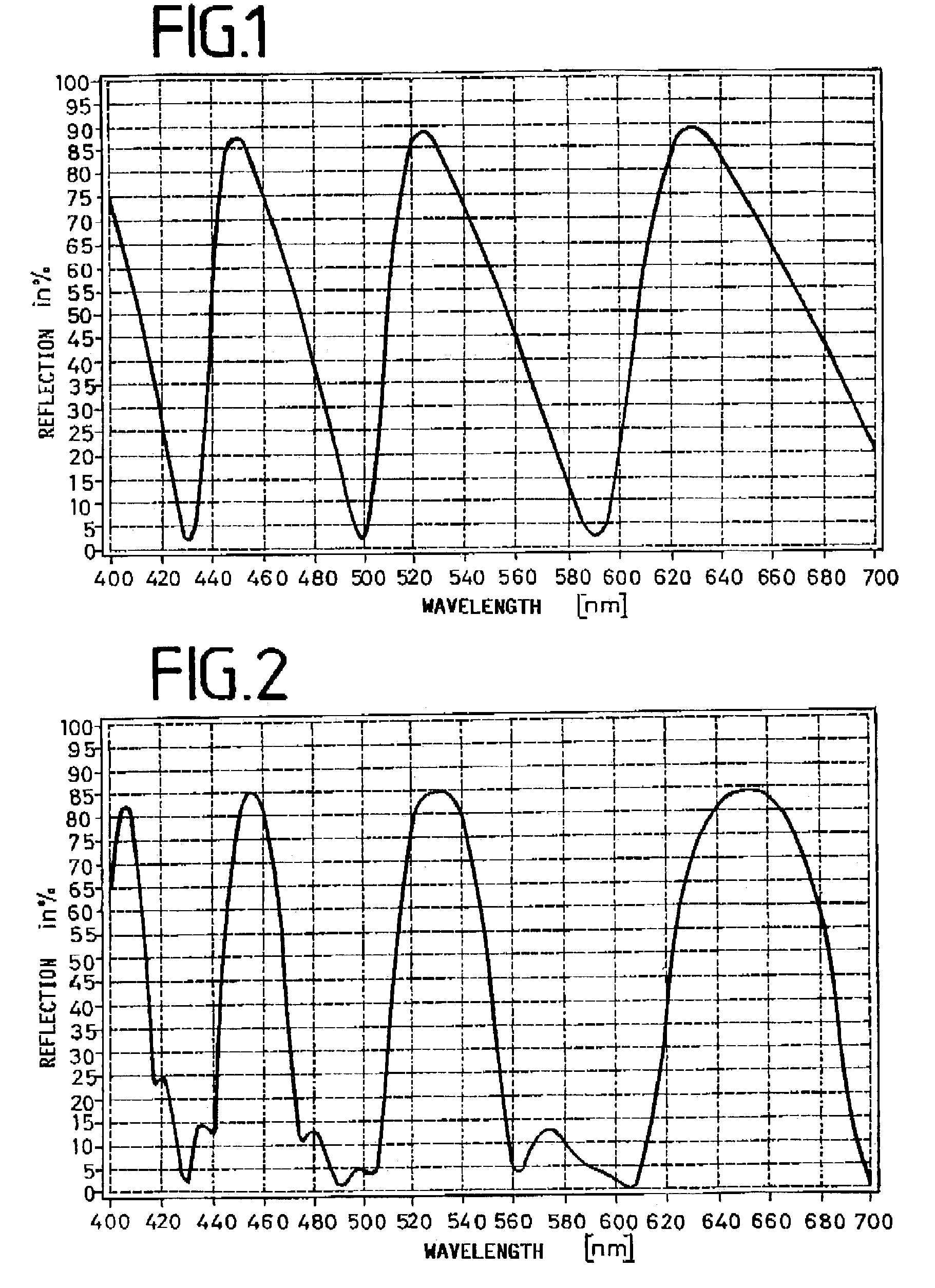
[0014]The invention consequently relates to a material with spectrally selective reflection in the primary valences of red, green and blue. This material is preferably applied onto laser projection screens in order to make projection possible even in daylight. In a first solution, onto a substrate, for example glass or synthetic material, a first layer of aluminum is applied, which is followed by a second layer of SiO2, on which, in turn, a layer of NiCr is disposed. The latter is in contact with air. A second solution comprises five layers, of which the first is comprised of TiO2, the second of SiO2, the third of TiO2 the fourth of SiO2 and the fifth of TiO2. The first layer is here connected with the substrate, while the fifth layer is in contact with air. The first solution is much simpler than the second solution.
[0017]The advantage attained with the invention comprises in particular that utilizing only three layers, one metallic layer and two dielectric layers, the above stated requirements are met in a laser image screen. It is here especially advantageous that the metallic layer can be produced cost-effectively, for example by vapor deposition in film coating installations. In comparison to sputter processes the metal layer can be applied at approximately the 10- to 100-fold rate. The dielectric layer can alternatively be applied with the cost-effective vapor deposition technology or the sputter technology. The requirements are alternatively also fulfilled with the aid of a five-layer system of dielectric materials with a high index of refraction. However, the production of the five-layer system is significantly more costly than the production of the three-layer system. Both layer systems can be readily produced as a large-area system by means of a DC or a medium frequency sputter process. Consequently the expensive production of the fully dielectric layer systems commonly used up to now becomes superfluous. The reproducibility of the layer thickness and the indices of refraction is better than 1%.

Problems solved by technology

None of the filters listed above reflects spectrally selectively in the primary valences of red, green and blue, as a consequence of which the filters are not suitable for a laser projection screen.
However, the production of the five-layer system is significantly more costly than the production of the three-layer system.
Consequently the expensive production of the fully dielectric layer systems commonly used up to now becomes superfluous.

Method used


Image

  • Material with spectrally selective reflection
  • Material with spectrally selective reflection

Examples


Embodiment Construction

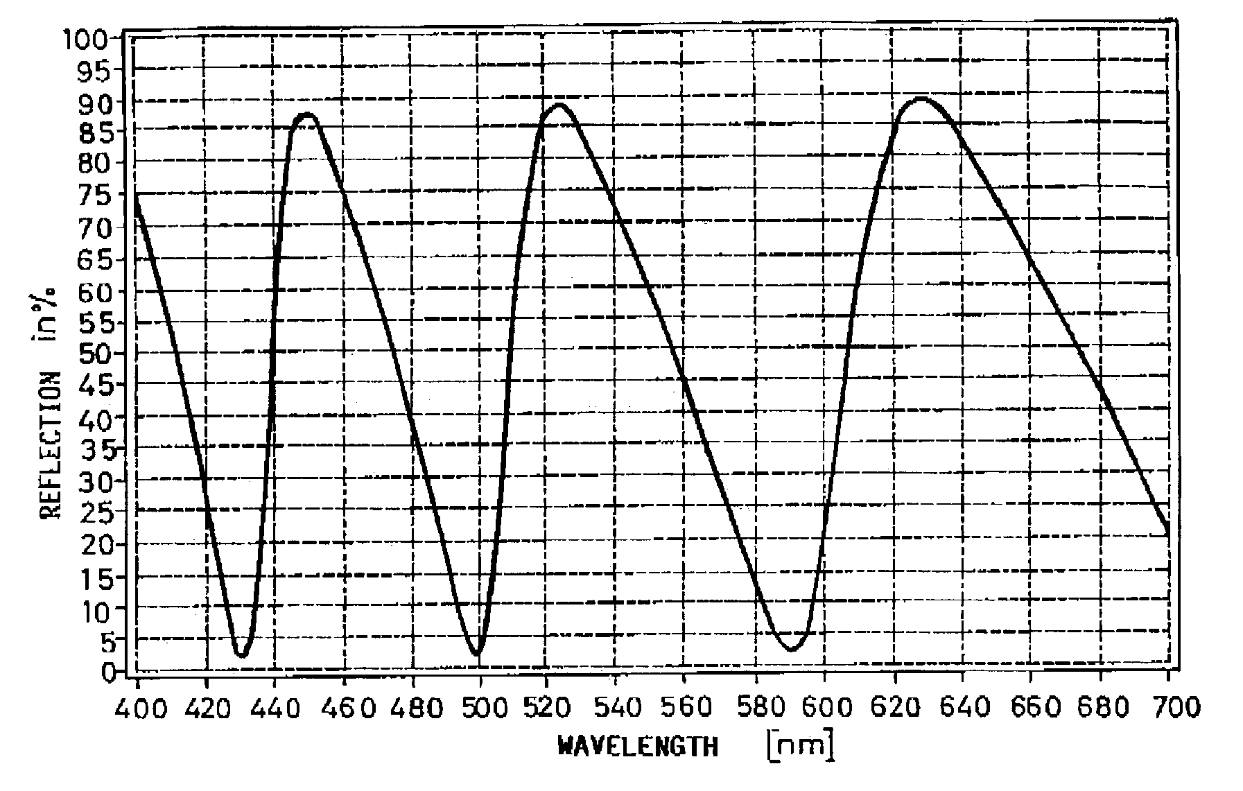
[0022]FIG. 1 depicts the reflection curve of a material comprised of three layers disposed one above the other, which is applied onto a substrate, for example onto glass or a synthetic material film. The first layer of this material, disposed directly on the substrate, is an aluminum layer having a thickness of approximately 100 nm, the second layer, disposed on the aluminum, is an SiO2 layer approximately 1030 nm thick, and the third layer, which is applied onto the SiO2 and which is in contact with air, is an NiCr layer approximately 30 nm thick. The first layer consequently is a layer highly reflecting over the entire range of visible light, while the second layer, which is disposed on the first layer, is a layer essentially non-absorbing over the entire range of visible light. Lastly the third layer is a layer, disposed on the second layer, which is partially transmissive over the entire range of visible light. This third layer is disposed above the other layers; the light to be...


PUM


Abstract

A material with spectrally selective reflection in the primary valences of red, green and blue is applied preferably onto laser projection screens in order to make possible the projection even in daylight. In a first embodiment, a first layer of a material that is highly reflective over the entire range of visible light, e.g., aluminum is applied onto a substrate, e.g., glass or a synthetic material, followed by a second layer of a material that is essentially non-absorbing over the entire range of visible light, e.g., SiO2. A third layer in contact with air is applied to the second layer and is made of a material that is partially transmissive over the entire range of visible light, e.g., of NiCr An alternative embodiment comprise five layers, The first layer is made a material with a high index of refraction, e.g.; TiO2, a second of a material with a low index of refraction, e.g., SiO2, the third of a material with a high index of refraction, e.g., TiO2: a fourth of a material with a low index of refraction. e.g., SiO2, and a fifth layer of a material with a high index of refraction, e.g., TiO2.

Description

FIELD OF THE INVENTION[0001]The invention relates to a material with spectrally selective reflection, preferably in the valences of red, green and blue.BACKGROUND AND SUMMARY OF THE INVENTION[0002]Materials with specific optical properties are needed in numerous technical fields. For example specific layers are applied onto synthetic materials in order to generate mirror properties (DE 39 27 087 C2), or multilayer systems are applied onto window panes in order to provide thermal protection (DE 197 45 881 A1).[0003]Multilayer filter systems, which have specific reflection and / or transmission properties (WO 95 / 17690), are also employed in the case of liquid crystal displays. These filter systems comprise for example in each pixel region filters for red, green and blue, with each filter having a common dielectric broadband mirror. The difference between the filters consists in the tuning thickness between the mirrors for each filter. Use of the common dielectric broadband mirror simpli...

Claims


Application Information

Patent Timeline
Patent Type & Authority Patents(United States)
IPC IPC(8): G02B1/10
CPCG02B5/0858G02B27/142G02B5/286
Inventor LOTZ, HANS-GEORGSAUER, PETER
Owner APPLIED MATERIALS GMBH & CO KG
Learn More