
System and method for a guaranteed delay jitter bound when scheduling bandwidth grants for voice calls via cable network

a technology of delay jitter and guaranteed delay, which is applied in the field of guaranteed delay jitter bound when scheduling bandwidth grants for voice calls via the communication medium, can solve the problems of restricting the downstream communication of the doctorate, and achieve the effect of improving the overall system efficiency and high efficiency in transmission opportunities

Inactive Publication Date: 2006-09-12
AVAGO TECH INT SALES PTE LTD
View PDF9 Cites 10 Cited by
  • Summary
  • Abstract
  • Description
  • Claims
  • Application Information

AI Technical Summary

Benefits of technology

[0009]The scheduler of the invention strives to obtain high efficiency in transmission opportunities (e.g., granting bandwidth) to constant bit rate applications (e.g., voice calls), while meeting the quality of service requirements of constant bit rate applications. Voice data transmission has very stringent delay jitter bounds but it can tolerate a certain amount of delay jitter and latency. Thus, the scheduler makes use of this delay jitter and latency budget to increase the concatenation opportunities and in turn improve the overall system efficiency. The scheduler generates bandwidth grants with certain regularity but avoids the strong demand of an exact periodicity.

Problems solved by technology

DOCSIS downstream communication is quite restrictive in the way the control information is conveyed to the data provider (e.g., cable modem) via a DOCSIS CMTS scheduler.

Method used


Image

  • System and method for a guaranteed delay jitter bound when scheduling bandwidth grants for voice calls via cable network
  • System and method for a guaranteed delay jitter bound when scheduling bandwidth grants for voice calls via cable network
  • System and method for a guaranteed delay jitter bound when scheduling bandwidth grants for voice calls via cable network

Examples


Embodiment Construction

A. Overview of the Invention

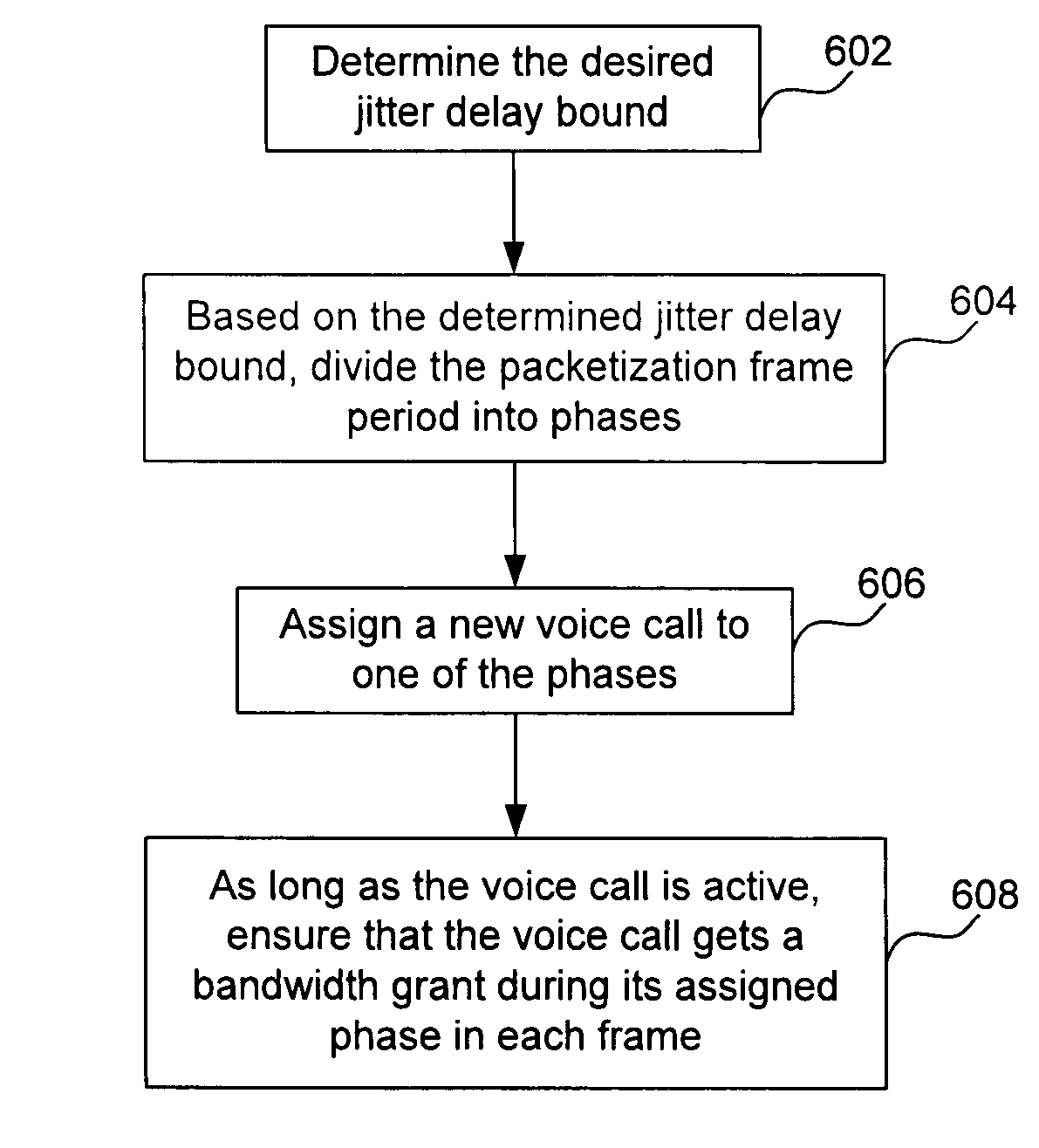
[0027]The scheduler of the invention strives to obtain high efficiency in granting transmission opportunities (e.g., bandwidth) to constant bit rate data applications (e.g., voice calls), while meeting the quality of service requirements of constant bit rate data applications. Note that the present invention is described as a transmission opportunity being a bandwidth grant and as a constant bit rate application being a voice call. This is not meant to limit the invention.

[0028]Voice data transmission has very stringent delay jitter bounds but it can tolerate a certain amount of delay jitter and latency. Thus, the scheduler makes use of this delay jitter and latency budget to increase the concatenation opportunities and in turn improve the overall system efficiency. The scheduler also reduces fragmentation of grants which also improves the overall system efficiency. The scheduler generates bandwidth grants with certain regularity but avoids the strong dem...


PUM


Abstract

A system and method for guaranteeing a delay jitter bound when scheduling bandwidth grants for voice calls via a communication medium is provided. The method includes the steps of: determining the delay jitter bound; based on the determined delay jitter bound, dividing a packetization frame period into phases; assigning a voice call to one of the phases; and scheduling a bandwidth grant to the voice call during the assigned phase, thereby guaranteeing the delay jitter bound. The system includes a scheduler, where the scheduler determines the delay jitter bound, divides a packetization frame period into phases based on the determined delay jitter bound, assigns a voice call to one of the phases, and schedules a bandwidth grant to the voice call during the assigned phase, thereby guaranteeing the delay jitter bound. A dejitter buffer implements a way to provide zero jitter service, even though the packet transmission on the cable network has jitter, by delaying the packet and thus converting jitter into delay.

Description

CROSS-REFERENCE TO RELATED APPLICATIONS[0001]The present application claims priority to provisional applications U.S. Pat. Ser. No. 60 / 262,202, filed Jan. 17, 2001, entitled “Dejitter Buffer at CMTS to Support Zero Jitter Voice in HFC Networks,” by Gummalla et al., (SKGF 1875.0690000) (incorporated by reference in its entirety herein) and U.S. Pat. Ser. No. 60 / 262,201, filed Jan. 17, 2001, entitled “Voice Scheduling Algorithms,” by Sala et al., (SKGF. 1875.0470000) (incorporated by reference in its entirety herein).[0002]The present application is a continuation-in-part application to non-provisional application U.S. Pat. Ser. No. 09 / 785,020 filed Feb. 15, 2001, entitled “Voice Architecture for Transmission Over a Shared, Contention Based Medium,” by Gummalla et al., (SKGF 1875.0470001) (incorporated by reference in its entirety herein).BACKGROUND OF THE INVENTION[0003]1. Field of the Invention[0004]The present invention is generally related to guaranteeing a delay jitter bound when...

Claims


Application Information

Patent Timeline
IPC IPC(8): H04L12/28H04L12/24H04L12/56H04L12/64H04L29/06H04M7/00H04N7/173H04N21/2385H04N21/426H04N21/437H04N21/439H04N21/442H04N21/4788H04N21/61H04N21/6377H04N21/647
CPCH04J3/0632H04L12/2874H04L12/5693H04L12/5695H04L12/6418H04L29/06H04L29/06027H04L41/5019H04L41/5087H04L47/10H04L47/15H04L47/2416H04L47/2433H04L47/283H04L47/35H04L47/56H04L47/6215H04L47/788H04L47/801H04L47/805H04L47/822H04L47/824H04L47/827H04L65/80H04M7/006H04N7/17309H04N21/2385H04N21/42676H04N21/437H04N21/4396H04N21/44209H04N21/4788H04N21/6118H04N21/6168H04N21/6377H04N21/64707H04L12/2801H04L69/08H04L41/0896H04L2012/6481H04L2012/6494H04L69/22H04L47/50H04L47/70H04L9/40H04L65/1101
Inventor GUMMALLA, AJAY CHANDRA VSALA, DOLORS
Owner AVAGO TECH INT SALES PTE LTD
Learn More