Eureka AIR delivers breakthrough ideas for toughest innovation challenges, trusted by R&D personnel around the world.

Active noise cancellation stability solution

a technology of active noise and stability solution, which is applied in the direction of fuel intake silencers, combustion air/fuel air treatment, instruments, etc., can solve the problems of system creating unwanted high-pitched sound, system prone to unwanted high-pitched sound, and temporarily disabled noise cancellation feature, so as to reduce engine noise, control noise attenuation, and avoid the effect of noise creation

Active Publication Date: 2006-09-12
SIEMENS VDO AUTOMOTIVE CORP
View PDF46 Cites 41 Cited by
  • Summary
  • Abstract
  • Description
  • Claims
  • Application Information

AI Technical Summary

Benefits of technology

[0007]The invention concerns a method and system of controlling noise attenuation. As known, to attenuate engine noise, a noise canceling signal is generated by a computer that emits this signal through a speaker in proximity to the source of the noise. When system conditions are detected that may result in the generation of an undesirable noise by the noise attenuation system, the noise cancellation feature is temporarily disabled. In this way, the method and system avoid the creation of an undesirable noise that is frequently generated by noise attenuation systems at times of low engine load.

Problems solved by technology

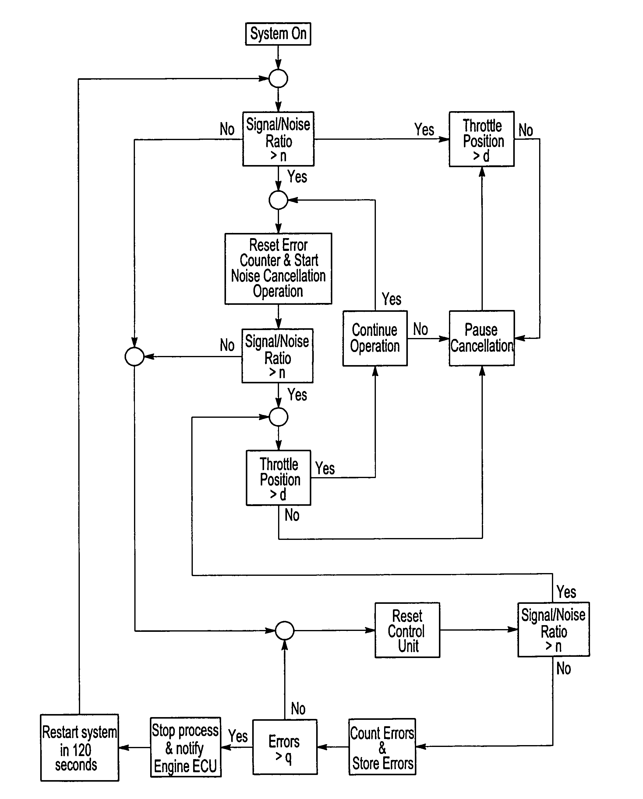
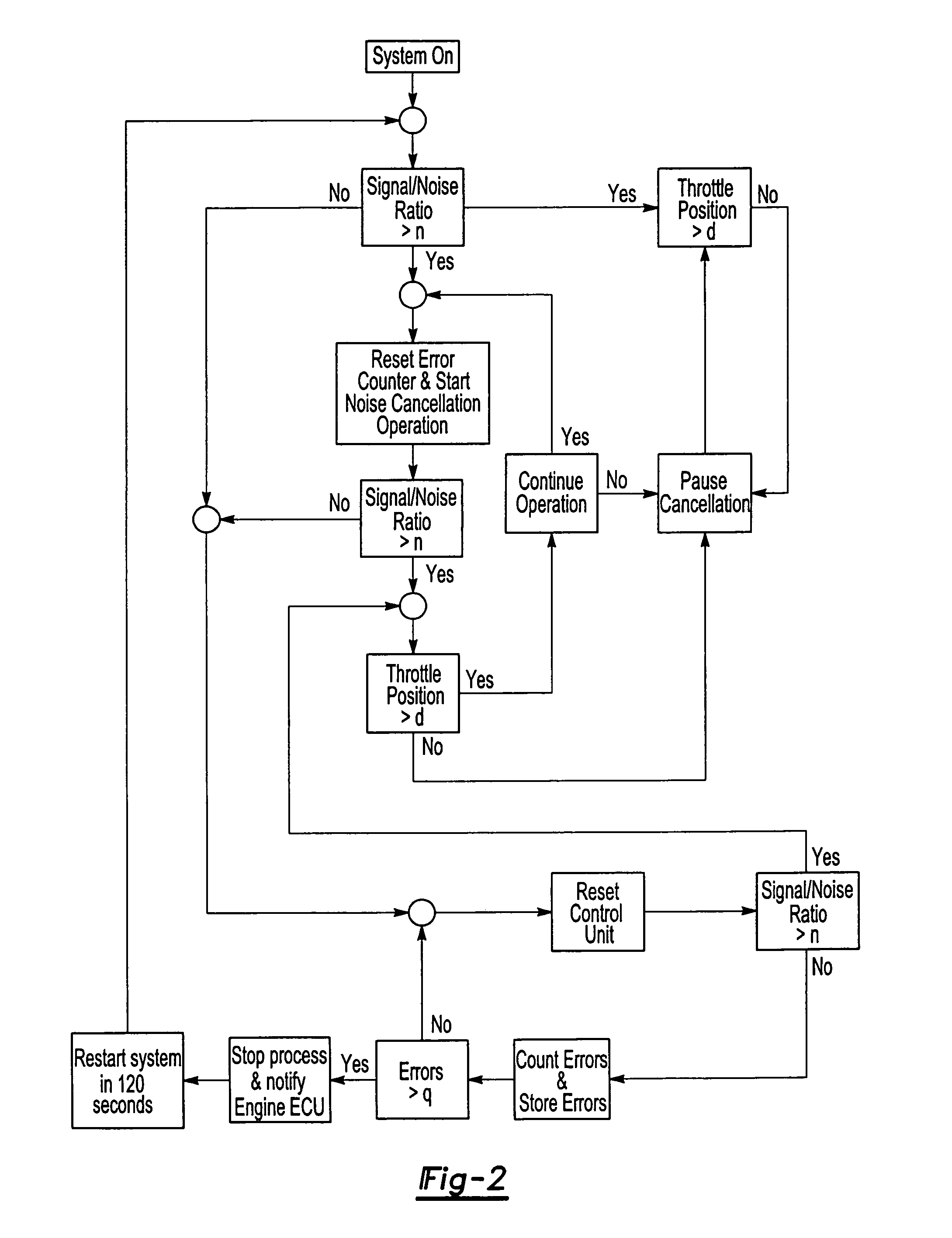
When system conditions are detected that may result in the generation of an undesirable noise by the noise attenuation system, the noise cancellation feature is temporarily disabled.
For example, if engine noise is low relative to background sound, the noise attenuation system is susceptible to the creation of an unwanted high pitch sound.
However, under certain circumstances, the system may create an unwanted noise as a consequence of system error.
In the event that the number of disables exceeds a preset level, then the noise attenuation system is disabled again and an error message is issued.

Method used


Image

  • Active noise cancellation stability solution
  • Active noise cancellation stability solution
  • Active noise cancellation stability solution

Examples


Embodiment Construction

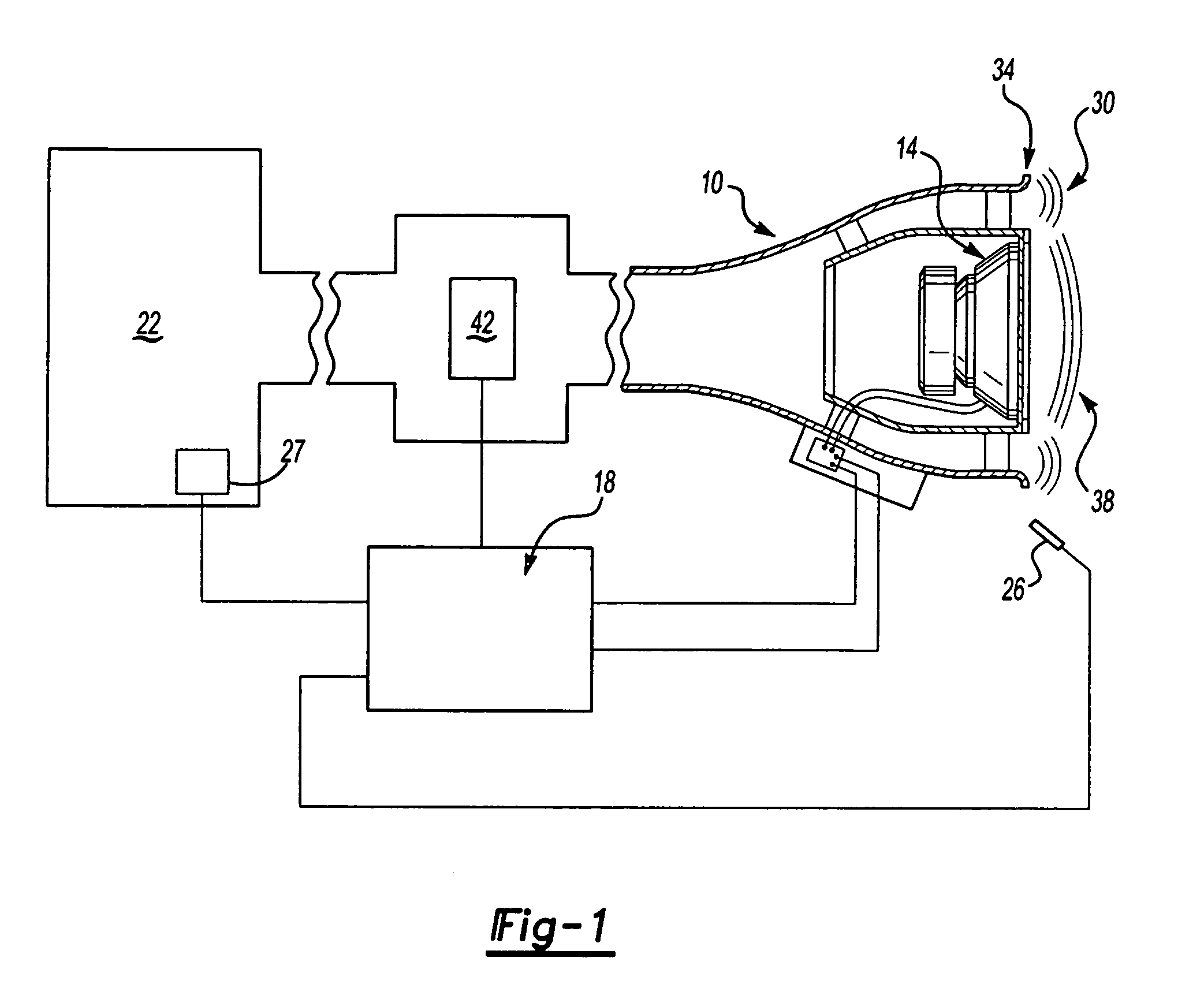
[0015]FIG. 1 illustrates the method and system of noise attenuation of an embodiment of the invention. Pictured schematically are air induction body 10 and speaker 14, preferably disposed in air induction body 10, control unit 18, engine 22, and sensor 26, here an error microphone, and reference sensor 27, such as an engine tachometer. Engine noise 30 from engine 22 travels through air induction body 10 out of mouth 34 of air induction body 10. As known, during normal operation, control unit 18 has a noise cancellation feature that generates a noise canceling signal 38 through speaker 14. Because noise canceling signal 38 is out of phase with engine noise 30, both noise canceling signal 38 and engine noise 30 are thereby attenuated.

[0016]The invention includes at least one sensor 26 for sensing a system condition, which is in communication with control unit 18. When a predetermined system condition is detected by sensor 26, the noise cancellation feature of control unit 18 is disabl...


PUM


Abstract

The method of noise attenuation comprises the steps of generating a noise canceling signal, sensing for an system condition, and ceasing the generation of the noise canceling based upon the system condition. This method is embodied in a system that includes an air induction body, a speaker in proximity to the air induction body, a sensor for sensing a system condition, and a control unit with a noise cancellation feature. The control unit is in communication with both the speaker and the sensor. Based upon the sensed system condition, the control unit may disable the noise cancellation feature.

Description

[0001]This application claims priority to Provisional Patent Application Ser. No. 60 / 195,026 filed Apr. 6, 2000.BACKGROUND OF THE INVENTION[0002]This invention relates to an active method and system for controlling automotive induction noise.[0003]Manufacturers have employed active and passive methods to reduce engine noise within the passenger compartment. Such noise frequently emanates from the engine, travels through the air induction system and emanates out of the mouth of the air intake into the passenger compartment. Efforts have been made to reduce the amount of engine noise traveling through the air induction system. These efforts include the use of both passive devices such as expansion chambers and Helmholtz resonators and active devices involving anti-noise generators.[0004]Active systems use a speaker to create a canceling sound that attenuates engine noise. The sound created is out of phase with the engine noise and combines with this noise to result in its reduction. G...

Claims


Application Information

Patent Timeline
IPC IPC(8): A61F11/06H04B1/00F01N1/06F02M35/12F02M35/16G10K11/178
CPCF01N1/065F02M35/10013F02M35/10118F02M35/161G10K11/178F02M35/125G10K11/1788G10K11/1784G10K2210/117G10K2210/121G10K2210/1282G10K2210/3016G10K11/17821G10K11/17825G10K11/17833G10K11/17883
Inventor ASTORINO, JOHN F.MCLEAN, IAN R.LAAK, TREVOR
Owner SIEMENS VDO AUTOMOTIVE CORP
Why Eureka
Eureka Blog
Learn More