Electronic aircraft braking system with brake wear measurement, running clearance adjustment and plural electric motor-actuator ram assemblies

a technology of electric motor and actuator ram, which is applied in the direction of braking system, aircraft braking arrangement, transportation and packaging, etc., can solve the problems of inherently imprecise, increased running clearance of actuator ram, and devices adding weight and complexity to the braking system

Inactive Publication Date: 2006-09-19
THE BF GOODRICH CO
View PDF25 Cites 44 Cited by
  • Summary
  • Abstract
  • Description
  • Claims
  • Application Information

AI Technical Summary

Benefits of technology

[0012]The present invention provides a brake system and method, particularly an electrically actuated aircraft brake system and method, which provides various advantages over known brake systems and methods.
[0017]As will be appreciated, an improved brake system arises from the use of either one or both of the above summarized wear measurement and running clearance features. In addition, these features are particularly useful in aircraft brake systems and particularly an electrically actuated aircraft brake system which does not need hydraulic components which are subject to various drawbacks including fluid leaks, high maintenance requirements, fire hazard, higher overall weight, etc.
[0018]According to another aspect of the invention, there is provided an electro-mechanical brake assembly comprising a brake disk stack; a housing including a guideway; a ram nut guided by the guideway for movement toward and away from the brake disk stack; a lead (preferably a ball) screw in threaded engagement with the ram nut whereupon rotation of the lead screw effects linear movement of the nut for selective movement into and out of forceful engagement with the brake disk stack for applying and releasing braking force on a rotatable wheel; and an electric motor drivingly connected to the lead screw gear for rotating the lead screw to effect movement of the ram nut toward and away from the brake disk stack. In contrast to prior art ram assemblies using, for example, a key or spline to prevent rotation of the ram as it moves linearly, the guideway and ram nut of the present invention respectively have polygonal cross-sections defined by plural outer side surfaces which rotationally interfere with one another to restrain rotation of the ram nut relative to the housing. This arrangement provides for maximum alignment and resistance to cocking and binding of the ram, while minimizing sliding friction.
[0020]According to another broad aspect of the invention, there is provided a brake system wherein a position sensor is used to determine braking load. In a preferred embodiment, the brake system comprises a brake disk stack; a reciprocating ram; a motive device operatively connected to the reciprocating ram for selectively moving the reciprocating ram into and out of forceful engagement with the brake disk stack for applying and releasing braking force on a rotatable wheel; a controller for controlling the motive device for selective control of the reciprocating ram and regulation of the force applied by the reciprocating ram against the brake disk stack; and a position sensor which supplies a position signal representative of, the position of the reciprocating ram; and characterized by the controller including circuitry for effecting displacement of the reciprocating ram to load the brake disk stack by a predetermined amount based on a present displacement value of the position signal obtained from the position sensor. This arrangement provides for optimum brake clamping force dynamic response, eliminates or minimizes hysteresis associated with other means of control, and enables the system to apply equal force on all actuators. The position sensor preferably includes a LVDT transducer connected between the reciprocating ram and a brake housing, and the motive device preferably includes a servo motor.

Problems solved by technology

As the brake disks wear, the running clearance of the actuator rams correspondingly increases.
While functional, these devices add weight and complexity to the braking system, and need to be overhauled usually each time the brake disk stack is replaced.
This arrangement requires a visual inspection of the pin to determine wear and is inherently imprecise.
Such a system requires a re-calibration of the position sensor after a power interruption which may result in loss of braking capability, long recovery time and possible uncommanded brake clamp force application.

Method used


Image

  • Electronic aircraft braking system with brake wear measurement, running clearance adjustment and plural electric motor-actuator ram assemblies
  • Electronic aircraft braking system with brake wear measurement, running clearance adjustment and plural electric motor-actuator ram assemblies
  • Electronic aircraft braking system with brake wear measurement, running clearance adjustment and plural electric motor-actuator ram assemblies

Examples


Embodiment Construction

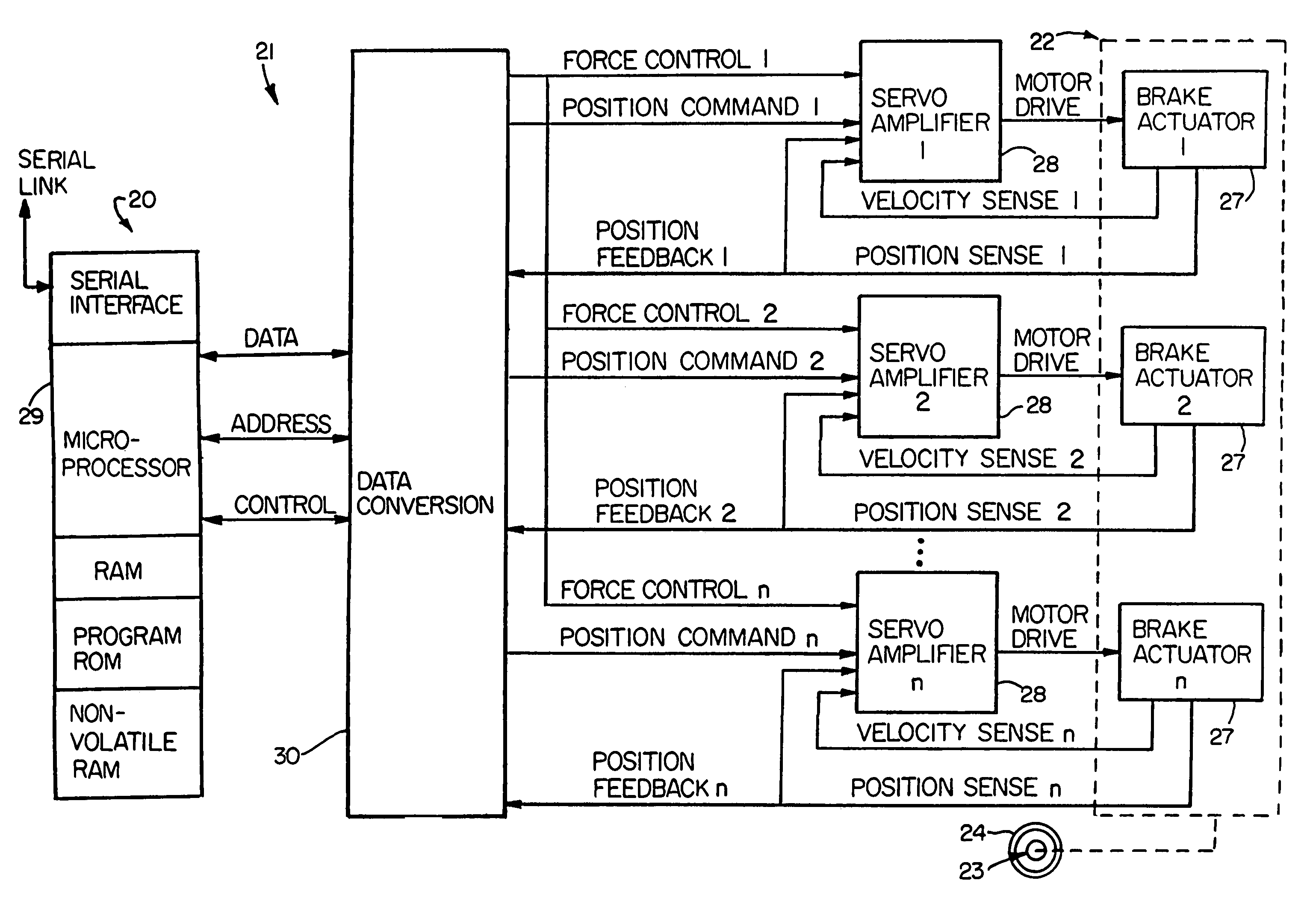
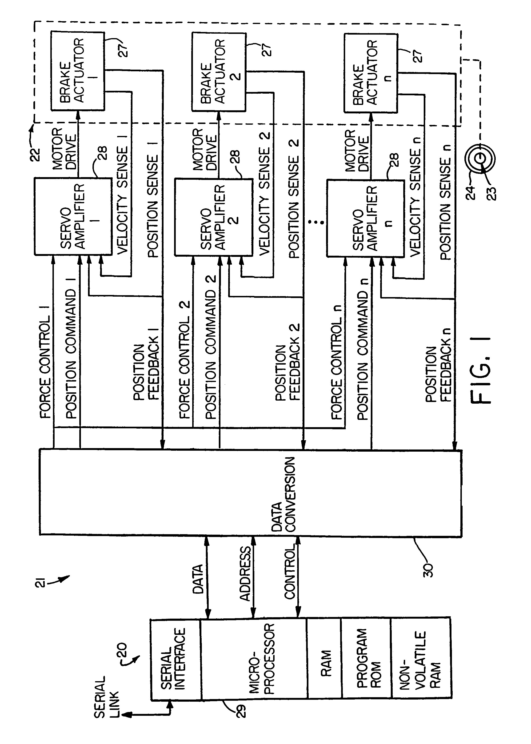
[0041]Referring now in detail to the drawings, FIG. 1 diagrammatically illustrates an exemplary multi-actuator computer controlled brake actuation system 20 to which the principles of the invention may be applied. The major functions of the system 20 are performed by a controller 21 and a brake actuator assembly 22. The brake actuator assembly 22 may be mounted in a conventional manner on a wheel and brake assembly 23 to apply and release braking force on a rotatable wheel 24 of such wheel and brake assembly. The present invention is particularly suited for use in aircraft braking systems, as will be appreciated by those skilled in the art.

[0042]Because the invention was conceived and developed for use in an aircraft braking system and particularly in association with the system 20, it will be herein described chiefly in this context. However, the principles of the invention in their broader aspects can be adapted to other types of systems including, for example, hydraulic systems w...


PUM


Abstract

An electrically actuated aircraft brake system and method which provides for brake wear measurement, brake running clearance adjustment, ram position-based control and improved construction and operation. Brake wear and running clearance measurement are obtained by analyzing the output of position sensing circuitry. The position sensing circuitry, preferably including a LVDT position sensor, is also used to determine braking load, a brake controller including circuitry for effecting displacement of one or more reciprocating rams to load a brake disk stack by a predetermined amount based on a present displacement value of the position signal obtained from the position sensor. The position sensor preferably includes a LVDT transducer connected between the reciprocating ram and a brake housing, and the motive device preferably includes a servo motor. Also provided is an actuator housing including a guideway for each ram, the guideway and ram having the same polygonal cross-section, whereby the ram nut is guided and restrained from rotation by the guideway as it is translated by a ball screw in threaded engagement with the ram nut for selective movement into and out of forceful engagement with the brake disk stack for applying and releasing braking force on a rotatable wheel. An electric motor is drivingly connected to each ball screw by a first gear integral with the ball screw, a second gear in mesh with the first gear, and a pinion on a rotating drive shaft of the electric motor.

Description

RELATED APPLICATION DATA[0001]This application is a continuation of U.S. patent application Ser. No. 10 / 268,409 filed Oct. 10, 2002 now U.S. Pat. No. 6,702,069, which is a continuation of U.S. patent application Ser. No. 09 / 486,687, filed Mar. 1, 2000 now U.S. Pat. No. 6,471,015, which is a continuation-in-part of U.S. patent application Ser. No. 08 / 853,513, filed May 9, 1997 now U.S. Pat. No 6,003,640. The aforesaid applications are hereby incorporated herein by reference in their entireties.FIELD OF THE INVENTION[0002]The invention herein described relates generally to brake control systems, more particularly to electronic braking systems, and still more particularly to aircraft braking systems.BACKGROUND OF THE INVENTION[0003]Known in the prior art are aircraft wheel and brake assemblies including a non-rotatable wheel support, a wheel mounted to the wheel support for rotation, and a brake disk stack having front and rear axial ends and alternating rotor and stator disks mounted ...

Claims


Application Information

Patent Timeline
Patent Type & Authority Patents(United States)
IPC IPC(8): F16D55/36B60T8/32B60T13/74B64C25/44F16D55/00F16D65/14F16D65/18F16D65/38F16D65/56F16D66/00F16D66/02
CPCB60T8/1703B60T8/885B60T13/74B64C25/44F16D55/36F16D65/18F16D65/56F16D66/00F16D66/02F16D66/021B60T8/325F16D2127/06F16D2055/0058F16D2055/0091F16D2065/386F16D2066/003F16D2066/005F16D2121/24F16D2125/40F16D2125/48F16D2125/52
Inventor RALEA, MIHAICHRIST, FRANKLIN C.
Owner THE BF GOODRICH CO
Why Eureka
Try Eureka