Solar tracking system

a solar tracking and solar energy technology, applied in the field of solar energy tracking systems, can solve the problems of reducing collection efficiency, reducing collection efficiency, and reducing the effect of manufacturing tolerances,

Inactive Publication Date: 2006-09-19
SOLAR SYST PTY LTD
View PDF30 Cites 86 Cited by
  • Summary
  • Abstract
  • Description
  • Claims
  • Application Information

AI Technical Summary

Benefits of technology

[0023]Preferably said comparison means is operable to control said alignment to maximize the sum of said first and second output signals.
[0025]Thus, if the detectors are located, say, either side of a shadow means, or each is provided with a plurality of side walls located to cast a shadow on that detector if misalignment occurs, at least one of the detector's outputs will drop with angle of misalignment θ much faster than by merely cos θ (in the example of a plane detector approximately perpendicular to the direction of the sun), thereby making the system more sensitive to misalignment.
[0028]Preferably said control mean is operable to control said alignment so as to protect said instrument from overheating if any one or more of said first output, said second output or said comparison indicates that said instrument is, or is in danger of, overheating.
[0042]Preferably said method includes controlling said alignment so as to protect said instrument from overheating if any one or more of said first output, said second output or said comparison indicates that said instrument or a part thereof is, or is in danger of, overheating.

Problems solved by technology

Such installation time and expense may not be acceptable in other applications, such as the installation of solar power collectors on a mass scale.
These existing approaches, however, make no allowance for the subsequent effects of imperfect manufacturing tolerances on the orientation of the radiation receiver (to which the collector directs collected radiation) relative to the collector itself.
If a plane mirror is used, errors in tracking precision of even 5° may not excessively reduce collection efficiency.
However, where the solar flux is concentrated (possibly by a factor of as much as three or more), a 5° tracking error may produce unacceptably high looses in collection efficiency.

Method used


Image

  • Solar tracking system
  • Solar tracking system
  • Solar tracking system

Examples


Embodiment Construction

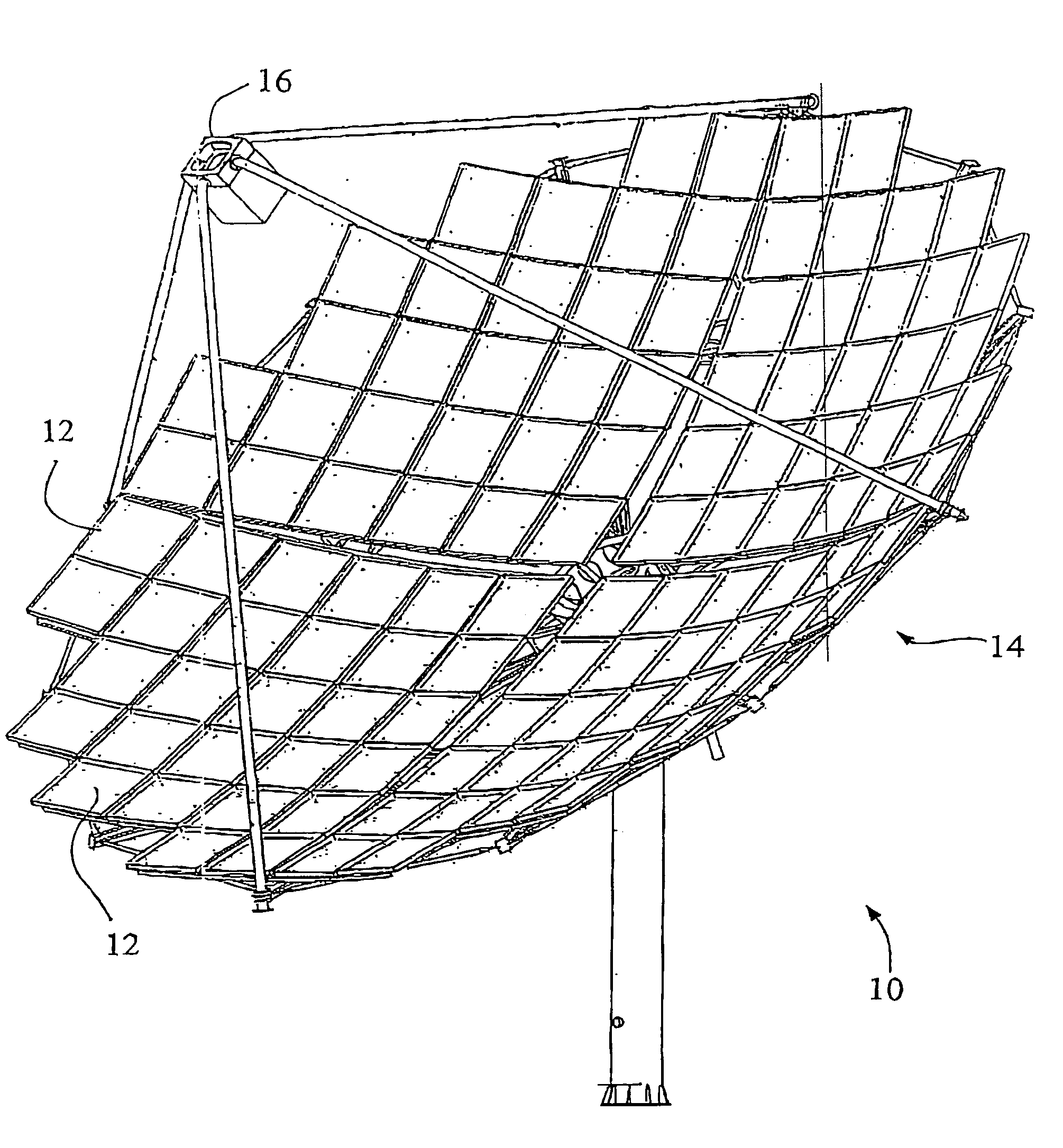
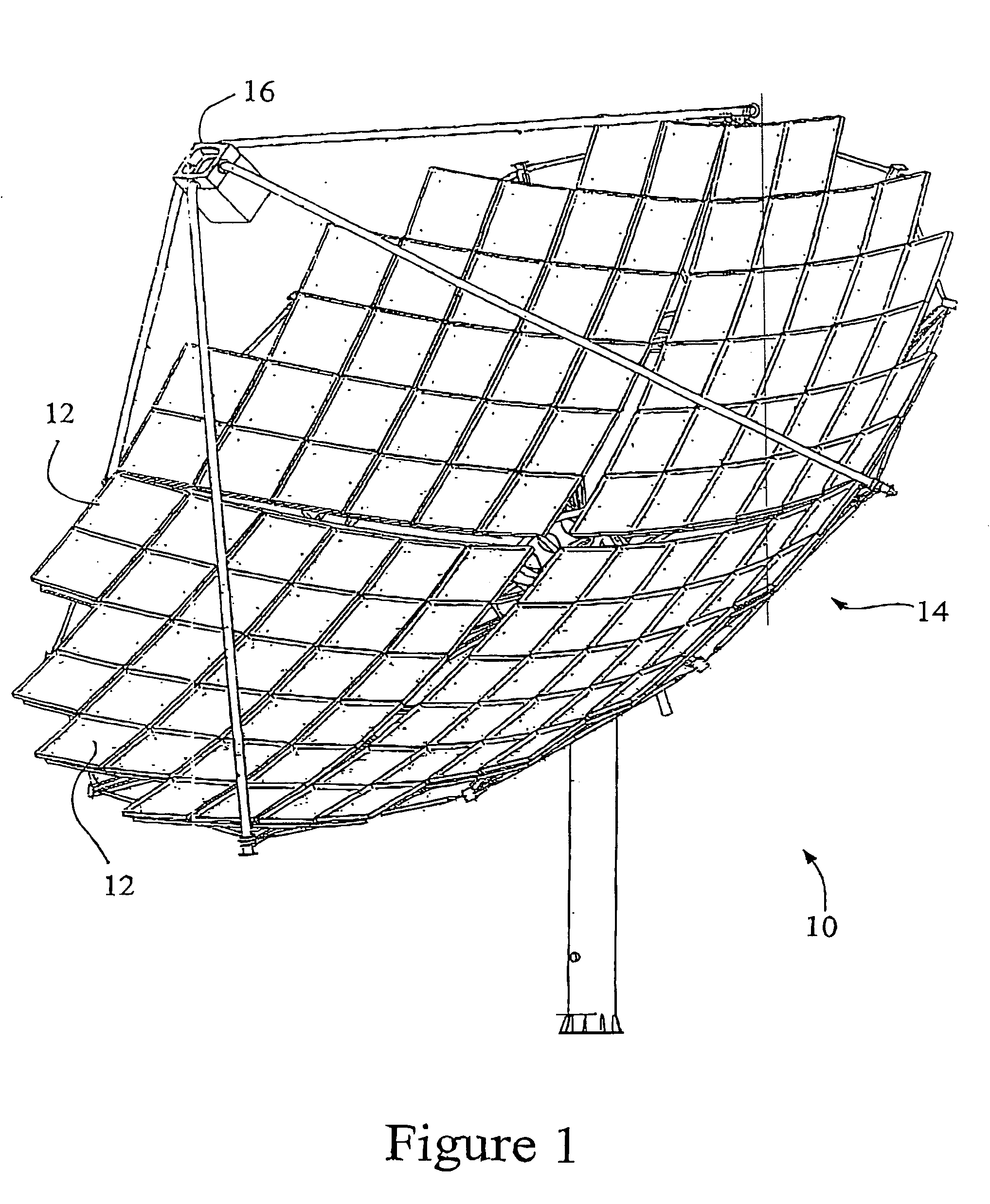
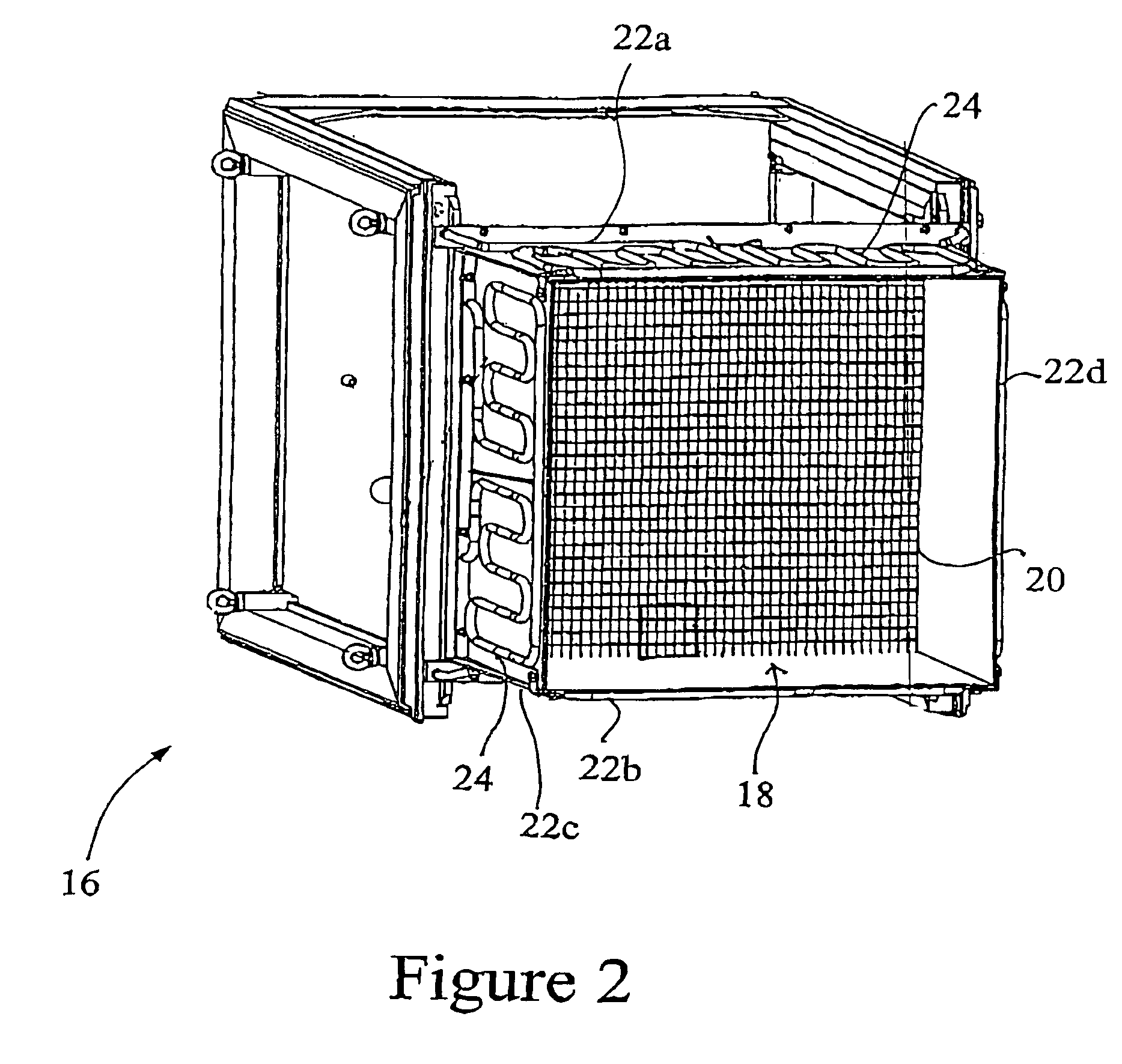
[0057]A solar electric power generator of a type for controlling by means of a solar tracking control system according to an embodiment of the present invention is illustrated schematically at 10 in FIG. 1. The generator 10 includes an array of focussing mirrors 12 forming a dish 14, and a receiver 16 substantially at the focus of the dish 14. The receiver 16 includes an array of photovoltaic cells (see FIG. 2). The solar tracking control system is principally intended to maximize the power output of the generator 10. It should be noted, as will be understood by those in the art, that the optimal alignment in such an application may not be directly at the sun. Asymmetries in or misalignment of the dish 14 and receiver l6 of the solar electric power generator may mean that the greatest power output is achieved with an alignment that, by conventional measures, is not directly—or apparently directly—at the sun.

[0058]Referring to FIG. 2, the receiver 16 comprises a square array 18 of ph...


PUM


Abstract

The invention provides a solar tracking system for controlling the alignment of an instrument with respect to the sun, the instrument having a solar radiation receiver and a solar radiation collector for collecting solar radiation and directing the radiation towards the receiver, the system having: at least first and second detectors locatable so as to move with the receiver and receive radiation from the collector, for generating respective first and second output signals according to their respective exposure to solar radiation from the collector; a comparison means for comparing the first and second outputs and producing a comparison signal indicative thereof; and control means for controlling the alignment of the instrument according to the comparison signal.

Description

CROSS REFERENCE TO RELATED APPLICATIONS[0001]This is the National Stage of International Application No. PCT / AU0200404, filed Mar. 28, 2002, and claims the benefit of Australian Patent Application No. PR4039, filed Mar. 28, 2001.FIELD OF THE INVENTION[0002]The present invention relates to a system and method for tracking the sun, of particular but by no means exclusive application in telescopes and solar power collectors.BACKGROUND OF THE INVENTION[0003]Existing techniques for tracking the sun rely typically on one or more of three methods. The diurnal motion of the sun is well understood, and consequently a telescope, for example, can be mounted on an accurately aligned alt-azimuth or equatorial mount. The axial drives of that mount are then computer controlled to maintain the telescope in an orientation that will point the objective lens or mirror of the telescope at the sun's calculated position.[0004]This approach, however, requires the highly accurate initial alignment of the m...

Claims


Application Information

Patent Timeline
Patent Type & Authority Patents(United States)
IPC IPC(8): G01J1/20G01C21/02G01C21/24F24S50/20G05D3/10
CPCF24J2/38G05D3/105Y02E10/47F24S50/20
Inventor LASICH, JOHN BEAVIS
Owner SOLAR SYST PTY LTD
Why Eureka
Try Eureka