Micro beam collimator having an iris like capillary for compressing beams

a beam collimator and micro-beam technology, which is applied in the direction of instruments, nuclear engineering, and handling using diaphragms/collimeters, can solve the problems of affecting the operation of the beam collimator. the effect of easy adjustment of the cross section width

Inactive Publication Date: 2006-09-19
EURATOM
View PDF7 Cites 2 Cited by
  • Summary
  • Abstract
  • Description
  • Claims
  • Application Information

AI Technical Summary

Benefits of technology

[0008]The invention provides a micro beam collimator for compressing beams which allows easy adjustment of the width of the

Problems solved by technology

Of course, construction of a metallic capillary tube in the style of the classic glass capillary with very smooth inner wall is extremely difficult.
However, changing the width of the cross section of the channel by replacin

Method used


Image

  • Micro beam collimator having an iris like capillary for compressing beams
  • Micro beam collimator having an iris like capillary for compressing beams
  • Micro beam collimator having an iris like capillary for compressing beams

Examples


Embodiment Construction

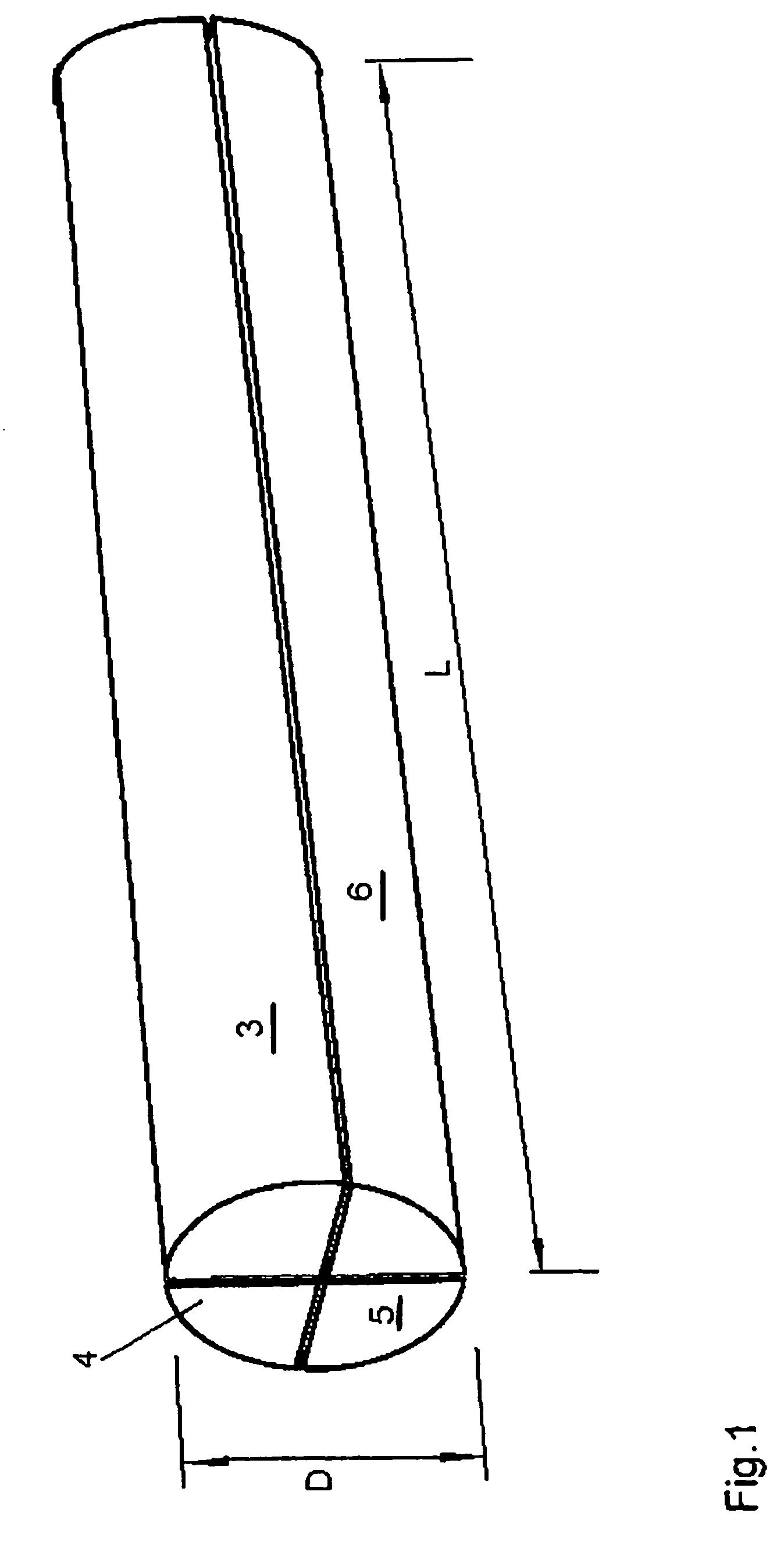
[0031]In FIG. 1 a tungsten rod having a circular cross section, a length of L=200 mm and a diameter of D=10 mm is shown. In case of the present embodiment this tungsten rod is cut longitudinally into four identical pieces so that four identical rod members 3,4,5 and 6 each having a cross section of a 90°-arc sector are prepared. The angle extent of the arc sector of the cross section of the rod members 3,4,5 and 6 is smaller or larger than 90° if more or less than four rod members are prepared. Alternatively, the cross section of the rod members 3,4,5 and 6 may have any kind of appropriate shapes, for example triangle, quadrate or rectangular shape.

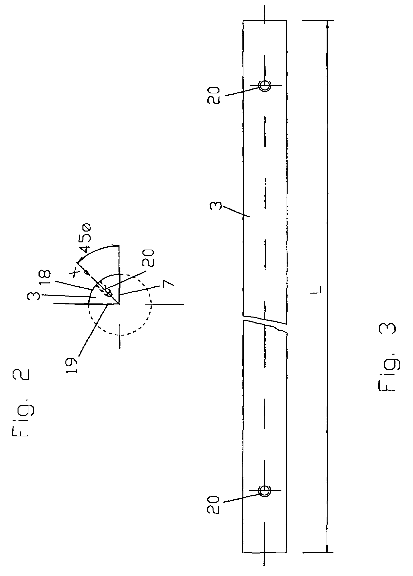
[0032]FIG. 2 shows a cross sectional view of rod member 3 in exemplary manner. The rod member 3 has a bordering surface 7 and a side surface 19 extending perpendicular to each other. Further, rod member 3 has a curved outer contact surface 18 which is engaged by adjustment screws as describe hereinafter. After careful construction, and if...


PUM


Abstract

“A micro beam collimator for compressing beams is described, where the collimator has channel means for providing a channel having a cross section and guiding the beams from an entrance end to an exit end of the channel. The invention provides a micro beam collimator for compressing beams which allows easy adjustment of the width of the cross section of the beams while making it possible at the same time to adjust the length of the cross section of the beams. The invention forms the channel means by at least three rod members each of which having at least one bordering surface for bordering the cross section, wherein the rod members are moveable against each other along the bordering surfaces so that the geometry of the cross action is variable.”

Description

BACKGROUND OF THE INVENTION[0001]The present invention relates to a micro beam collimator having an iris like capillary for compressing or concentrating beams. The invention is applicable for the formation of X-ray micro beams or neutron micro beams. Further fields of application are X-ray lithography and the fabrication of miniature mechanical devices.[0002]It is known in the art to use a glass capillary for the formation of X-ray micro beams to provide high resolution in many studies related to material characterization. All prior art developments rely on the principal of total multiple reflections of X-rays from the smooth internal glass capillary surface.[0003]High-resolution X-ray examination on ultra small regions of materials extended the application of numerous laboratory and industrial techniques, such as diffraction, spectroscopy, fluorescence, as well as metal refining, semiconductor and ceramic manufacturing [see prior art references 1,2]. The increasing interest in X-ra...

Claims


Application Information

Patent Timeline
IPC IPC(8): G21K1/02G21K1/04
CPCG21K1/04
Inventor PAPAIOANNOU, DIMITRIOSPAPAIOANNOU, CHRISTOSSTUTZ, HEINZ
Owner EURATOM
Why Eureka
Try Eureka