Structurally integrated antenna aperture and fabrication method

a technology of antenna aperture and fabrication method, applied in the direction of polarised antenna unit combination, resonant antenna, structural form of radiating elements, etc., can solve problems such as no function, and achieve the effect of facilitating electrical connection

Active Publication Date: 2006-09-19
THE BOEING CO
View PDF11 Cites 35 Cited by
  • Summary
  • Abstract
  • Description
  • Claims
  • Application Information

AI Technical Summary

Benefits of technology

[0006]The antenna aperture of the present invention forms a grid of antenna elements that can be manufactured, and scaled, to suit a variety of antenna and / or sensor applications. In one preferred form the antenna aperture comprises a honeycomb-like structure having an X-Y grid-like arrangement of dipole radiating elements. The antenna aperture does not require any metallic, parasitic supporting structures that would ordinarily be employed as support substrates for the radiating elements, and thus avoids the parasitic weight that such components typically add to an antenna aperture.
[0008]The strips are then placed in a tool or fixture and adhered together to form a grid-like structure. In one preferred implementation slots are cut at various areas along each of the strips to better enable interconnection of the strips at various points along each strip. In another preferred implementation portions of each strip are cut away such that edge portions of each electromagnetic radiating element form “teeth” that even better facilitate electrical connection to the radiating elements with external electronic components.

Problems solved by technology

Often these components comprise aluminum blocks or other like substructures that add “parasitic” weight to the overall antenna aperture, but otherwise perform no function other than as a support structure for a portion of the antenna aperture.

Method used


Image

  • Structurally integrated antenna aperture and fabrication method
  • Structurally integrated antenna aperture and fabrication method
  • Structurally integrated antenna aperture and fabrication method

Examples


Embodiment Construction

[0078]The following description of the preferred embodiment(s) is merely exemplary in nature and is in no way intended to limit the invention, its application, or uses.

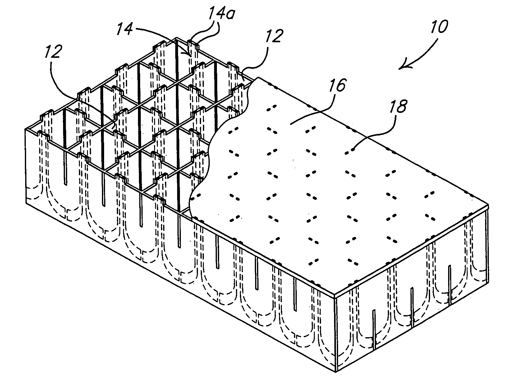
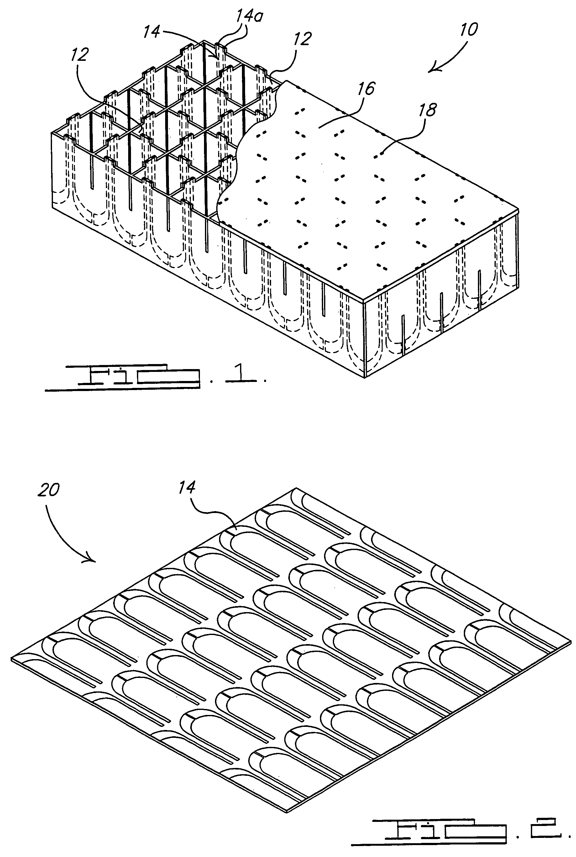
[0079]Referring to FIG. 1, there is shown an antenna aperture 10 in accordance with a preferred embodiment of the present invention. The antenna aperture 10 essentially forms a load bearing honeycomb-like structure that can be readily integrated into composite structural portions of mobile platforms without affecting the overall strength of the structural portion, and without adding significant additional weight beyond what would be present with a conventional honeycomb core, sandwich-like construction technique that does not incorporate an antenna capability.

[0080]The aperture 10 includes a plurality of wall sections 12 interconnected to form a honeycomb or grid-like core section. Each wall section 12 includes a plurality of electromagnetic radiating elements 14 embedded therein. While FIG. 1 illustrates an X-Y grid-...


PUM


Abstract

A phased array antenna aperture able to form a structural, load bearing portion of another structure, for example, a portion of a mobile platform. The antenna aperture is formed with a plurality of radiating elements sandwiched between prepreg fabric plies to form independent wall sections having a plurality of electromagnetic radiating elements embedded therein. The wall sections are secured in a honeycomb arrangement to form an array of cells of radiating elements. The manufacturing methods described herein enable arrays of widely varying sizes and shapes to be created and used as structural, load bearing portions of a wing, fuselage, door panel or other area of a mobile platform. The antenna aperture is lightweight because it does not include the weight of parasitic support components typically required in the construction of phased array antenna apertures.

Description

CROSS REFERENCE TO RELATED APPLICATIONS[0001]This application includes subject matter related to the following U.S. applications filed concurrently with the present application: Ser. No. 10 / 970,702; Ser. No. 10 / 970,703 now U.S. Pat. No. 7,046,209; and Ser. No. 10 / 970,722, all of which are incorporated by reference into the present application.FIELD OF THE INVENTION[0002]The present invention relates to antenna systems, and more particularly to an antenna aperture constructed in a manner that enables it to be used as a structural, load-bearing portion of a mobile platform.BACKGROUND OF THE INVENTION[0003]Present day mobile platforms, such as aircraft (manned and unmanned), spacecraft and even land vehicles, often require the use of an antenna aperture for transmitting and receiving electromagnetic wave signals. The antenna aperture is often provided in the form of a phased array antenna aperture having a plurality of antenna elements arranged in an X-Y grid-like arrangement on the mo...

Claims


Application Information

Patent Timeline
Patent Type & Authority Patents(United States)
IPC IPC(8): H01Q21/26
CPCH01Q13/08H01Q21/064H01Q21/0087
Inventor MCCARVILLE, DOUGLAS AHERNDON, GERALD FMARSHALL, IV, JOSEPH AVOS, ROBERT GBAKKER, ISAAC RBANKS, DAVID L
Owner THE BOEING CO
Why Eureka
Try Eureka