Spectrometer for measuring inelastically scattered light

a spectrometer and light scattering technology, applied in radiation pyrometry, instruments, analysis by subjecting materials to chemical reactions, etc., can solve the problem of compactness of probes, and achieve the effect of simple construction of probes, simple adaptation of probes, and increased possibilities

Inactive Publication Date: 2006-09-19
RIVER DIAGNOSTICS
View PDF9 Cites 8 Cited by
  • Summary
  • Abstract
  • Description
  • Claims
  • Application Information

AI Technical Summary

Benefits of technology

[0018]The use of hollow light guides based on this invention as a basis for Raman probes renders the construction of these probes simple and increases the possibilities for simple adaptation of probes to application-specific requirements, with regard to the light source to be used and properties of the sample to be examined as well as with regard to spatial resolution and location of the measured volume, by using specific optical elements at the distal extremity of the Raman probe.
[0019]An example of such provisions is a cone at the extremity of the light guide and tapering towards the sample, which makes it possible to capture light coming from the sample at a very large solid angle, whereupon in the cone, the solid angle is reduced, so that the light can be more readily guided further in the capillary.

Problems solved by technology

Due to this construction, the probe is very compact.

Method used


Image

  • Spectrometer for measuring inelastically scattered light
  • Spectrometer for measuring inelastically scattered light
  • Spectrometer for measuring inelastically scattered light

Examples


Embodiment Construction

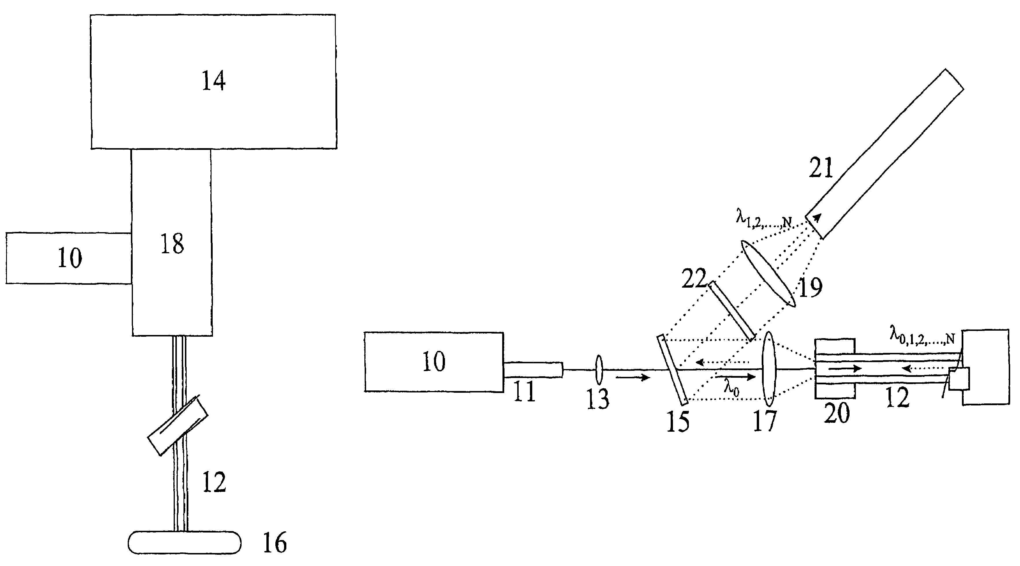
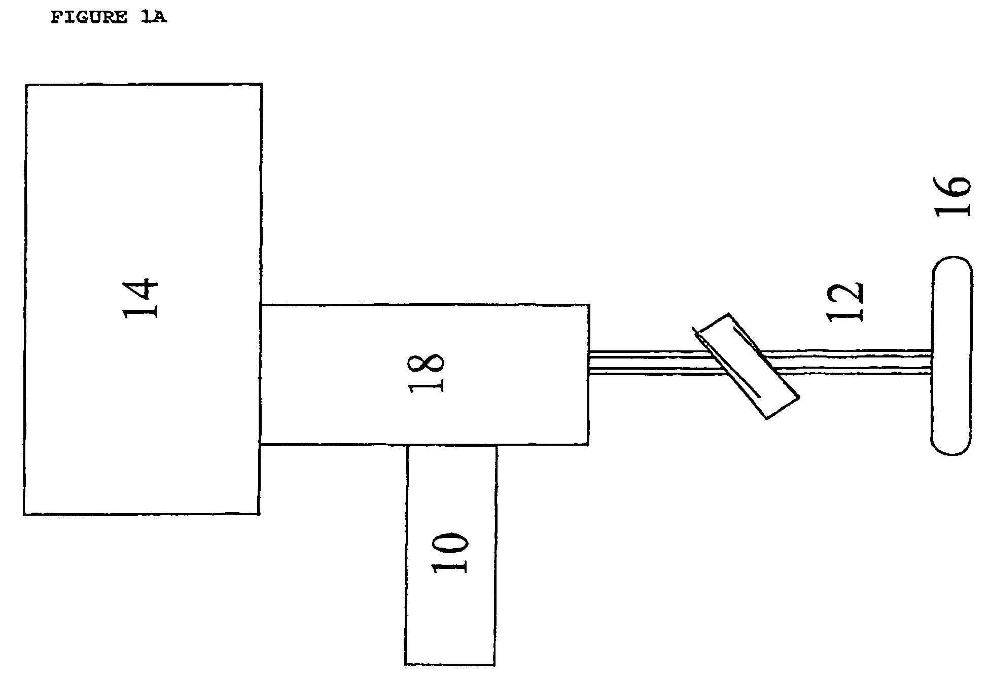
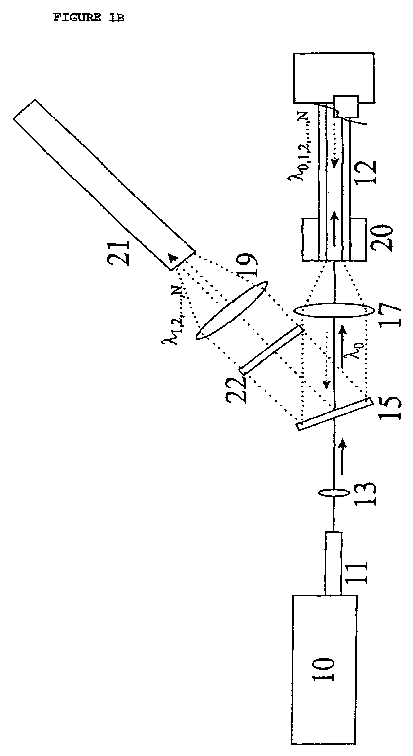
[0028]FIG. 1A shows a sample 16 and a spectrometer for measuring scattering on the sample 16. The spectrometer includes a light source 10, a probe with a hollow capillary 12, an analysis unit 14 and a coupling unit 18 which provides the coupling between the light source 10 and the light guide 12 on the one hand and between wave guide 12 and analysis unit 14 on the other hand.

[0029]In operation, with the light source 10, essentially monochromatic light is generated, which is guided via the coupling unit into the hollow light guide 12. This light is guided through the hollow light guide 12 to the sample 16. Light that has been scattered by the sample is guided through the probe, preferably through the hollow light guide, to the analysis unit. In the analysis unit 14, the intensity distribution of the light scattered by the sample 16 is measured as a function of the wavelength. Preferably, measurements are carried out on scattered light whose frequency is shifted by scattering with a s...


PUM

PropertyMeasurementUnit
lengthaaaaaaaaaa
diameteraaaaaaaaaa
refractive indexaaaaaaaaaa

Abstract

The spectrum of light, inelastically scattered by a sample (16) is measured. The light is guided through a capillary (12) from and to the sample, at least in one of these directions, through the channel no inelastic scattering of light occurs which can form an interfering background when measuring on the sample. By guiding the light through the channel, inelastic scattering of this light is prevented and it becomes possible to guide scattered light back through the channel to spectral analysis equipment (14) without problems with inelastic scattering during the guidance of the light. Preferably, the light is guided through the channel of the capillary in both directions.

Description

[0001]This application is the U.S. National Phase of International Application Number PCT / NL02 / 00386 filed on 12 Jun. 2002, which is incorporated herein by reference.BACKGROUND OF THE INVENTION[0002]The invention relates to a spectrometer for measuring inelastically scattered light. Raman spectrometers are an example of spectrometers for measuring inelastically scattered light. When a sample is irradiated with monochromatic light, the light scattered by the sample will contain wavelength components different from those present in the incident light. So-called Raman scattering of light on molecules present in the sample creates this effect. With a Raman spectrometer, a sample is illuminated with a strong, essentially monochromatic light source. The light which is scattered by the sample is collected and the spectral distribution is analysed for spectral components with a wavelength different from that of the light source.[0003]U.S. Pat. No. 5,862,272 describes the use of optic fibres...

Claims


Application Information

Patent Timeline
Patent Type & Authority Patents(United States)
IPC IPC(8): G01J3/44G01N21/65G01N21/77G02B6/26
CPCG01N21/65G02B6/262G01N2021/656G02B2006/0325G01N2201/0846
Inventor PUPPELS, GERWIN JAN
Owner RIVER DIAGNOSTICS
Why Eureka
Try Eureka