Method and system for source synchronous clocking

a source and clocking technology, applied in the field of synchronous clocking source, to achieve the effect of more accurate recovery of transmitted data over a network

Inactive Publication Date: 2006-09-19
CISCO TECH INC +1
View PDF11 Cites 44 Cited by
  • Summary
  • Abstract
  • Description
  • Claims
  • Application Information

AI Technical Summary

Benefits of technology

[0009]Advantageously, the source synchronous clocking provides more accurate recovery of transmitted data over a network. Additionally, this source synchronous clocking system advantageously eliminates the need for a phase-locked-loop to ensure clock and data synchronization between the ATM layer and the PHY layer. Furthermore, the source synchronous clocking discounts chip input and output delays.

Problems solved by technology

Furthermore, the source synchronous clocking discounts chip input and output delays.

Method used


Image

  • Method and system for source synchronous clocking
  • Method and system for source synchronous clocking
  • Method and system for source synchronous clocking

Examples


Embodiment Construction

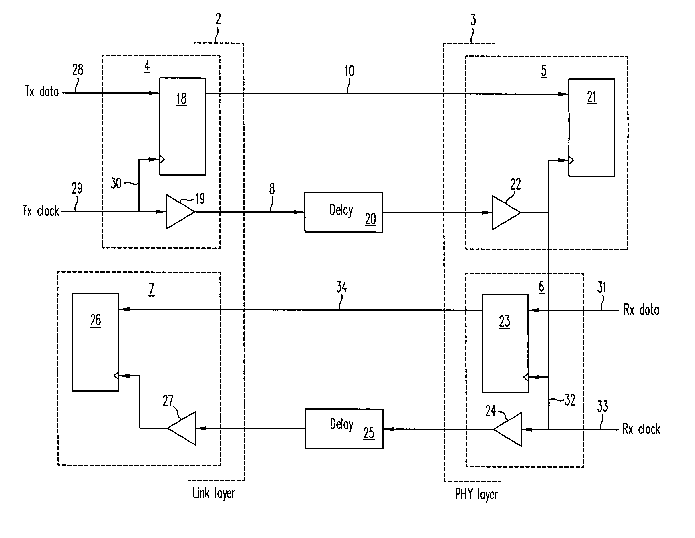
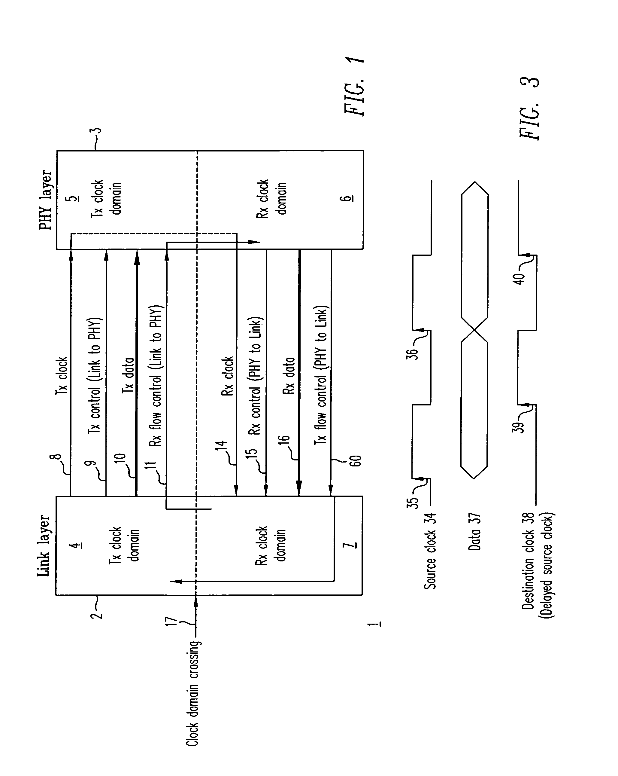
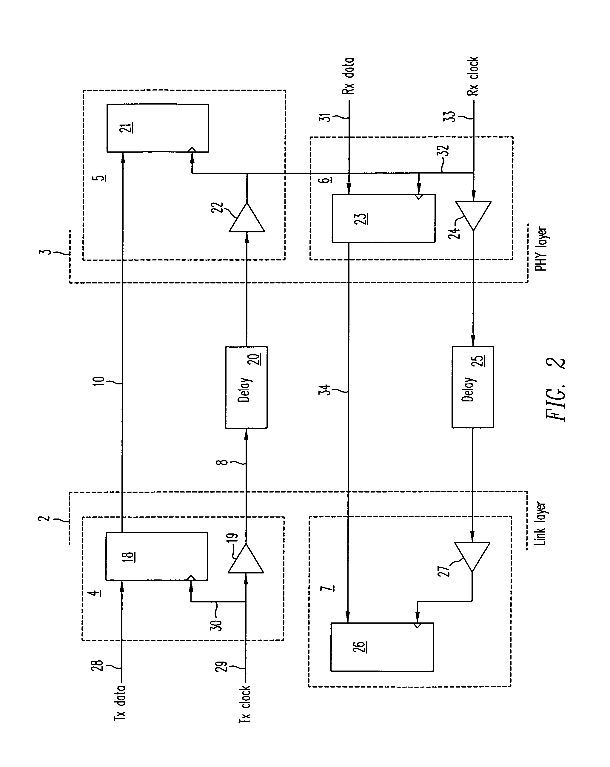
[0015]FIG. 1 is a block diagram of a source synchronous clocking system 1 for transferring signals between a link layer 2 to a PHY layer 3. The source synchronous clocking system 1 comprises a transmit (Tx) clock domain 4 and a receive (Rx) clock domain 7 in the link layer 2, and a transmit clock domain 5 and a receive clock domain 6 in the PHY layer 3. The link layer 2 comprises an ATM layer or frame layer. From the link layer 2 to the PHY layer 3, the following signals are transferred: a transmit clock 8, a transmit control 9, a transmit data 10, and a receive flow control 11. From the PHY layer 3 to the link layer 2, the following signals are transferred: a receive clock 14, a receive control 15, a receive data 16, and a transmit flow control 60.

[0016]The source synchronous clocking system 1 transfers information in two directions, a transmit direction and a receive direction. In the transmit direction, there is a transmit source which comprises a transmit clock domain 4 and a tr...


PUM


Abstract

A source synchronous clocking synchronizes data and clock signals transmitted between an ATM layer and a link layer. The source synchronous clocking includes a source clock domain in a first layer which includes a register having a first input for receiving a data signal, a second input for receiving a clock signal, and an output; and a buffer having an input for receiving the clock signal and an output, the buffer generating a delay that is substantially equivalent to a delay through the register. The source synchronous clocking further includes a destination clock domain in a second layer which includes a register having a first input and a second input, the first input of the register of the destination clock domain being coupled to the output of the register in the source clock domain.

Description

BACKGROUND INFORMATION[0001]1. Field of the Invention[0002]The invention relates to the field of telecommunication networks, and particularly, to Asynchronous Transfer Mode (ATM) interfaces between different communication layers.[0003]2. Description of Related Art[0004]As telecommunication networks companies design faster communication interfaces, the margin of error in synchronizing signals becomes narrower. Conventional interfaces use a clocking mechanism where receive and transmit clocks are driven from the ATM layer to the physical (PHY) layer. Examples of such interfaces include prior adopted or proposed Universal Test and Operation Physical Layer Protocol Interface for ATM (UTOPIA). Such clocking technique suffices for clock rate operation specified for earlier UTOPIA interfaces.[0005]In a source synchronous interface, a transmit clock signal from a link layer operates as a reference clock for all signals transmitted from the link layer to the PHY layer. A receive clock signal...

Claims


Application Information

Patent Timeline
Patent Type & Authority Patents(United States)
IPC IPC(8): H04L7/10
CPCH04L7/0008H04L7/0037H04L69/32H04L69/28H04L69/324H04L69/323
Inventor SETHURAM, JAYWEBER, RICHARD J.CHANDRA, JOSHI S.
Owner CISCO TECH INC
Why Eureka
Try Eureka