Control strategy for an internal combustion engine in a hybrid vehicle

Inactive Publication Date: 2006-09-19
FORD GLOBAL TECH LLC
View PDF34 Cites 34 Cited by
  • Summary
  • Abstract
  • Description
  • Claims
  • Application Information

AI Technical Summary

Benefits of technology

[0011]An advantage of the present invention is that by operating the engine at its most efficient operating condition while providing a secondary function, such as cabin cooling, the fuel penalty exacted by providing that secondary function is minimized. This is possible because the internal combustion engine, which is installed in a hybrid vehicle system, need not be constrained to develop torque which matches the power demanded by the driver.
[0012]A further advantage of the present invention is that torque fluctuations of the engine to provide transitions, for the purposes of a secondary device, may be made without affecting torque at the driving wheels. The process of making transitions is greatly simplified because engine torque need not be constant; the second machine of the hybrid system may absorb excess torque or provide makeup torque desired at the driving wheels. Furthermore, transitions may take place in a more fuel efficient manner than provided in prior art. Examples are transitions between lean and rich conditions to purge a LNT, transitions to and fro

Problems solved by technology

The secondary functions are typically attended to by operating the engine at a condition which provides the desired power but may be less than a desirable operating condition from the standpoint of providing the best function of the engine dependent auxiliary device, i.e., the device which provides the secondary function.
Increasing the power level of the engine is inefficient at many operating conditions.
Clearly, it would not be satisfactory to the operator of the vehicle to delay air conditioning until the engine happened to be at a desirable condition to facilitate efficient employment of the air conditioner.
Thus, in a conventional vehicle, the engine power is raised and a large fuel penalty may result.
There are engine operating conditions which could cause the carbonaceous material collected in the filter to spontaneously ignite and oxidize.
However, al

Method used


Image

  • Control strategy for an internal combustion engine in a hybrid vehicle
  • Control strategy for an internal combustion engine in a hybrid vehicle
  • Control strategy for an internal combustion engine in a hybrid vehicle

Examples


Embodiment Construction

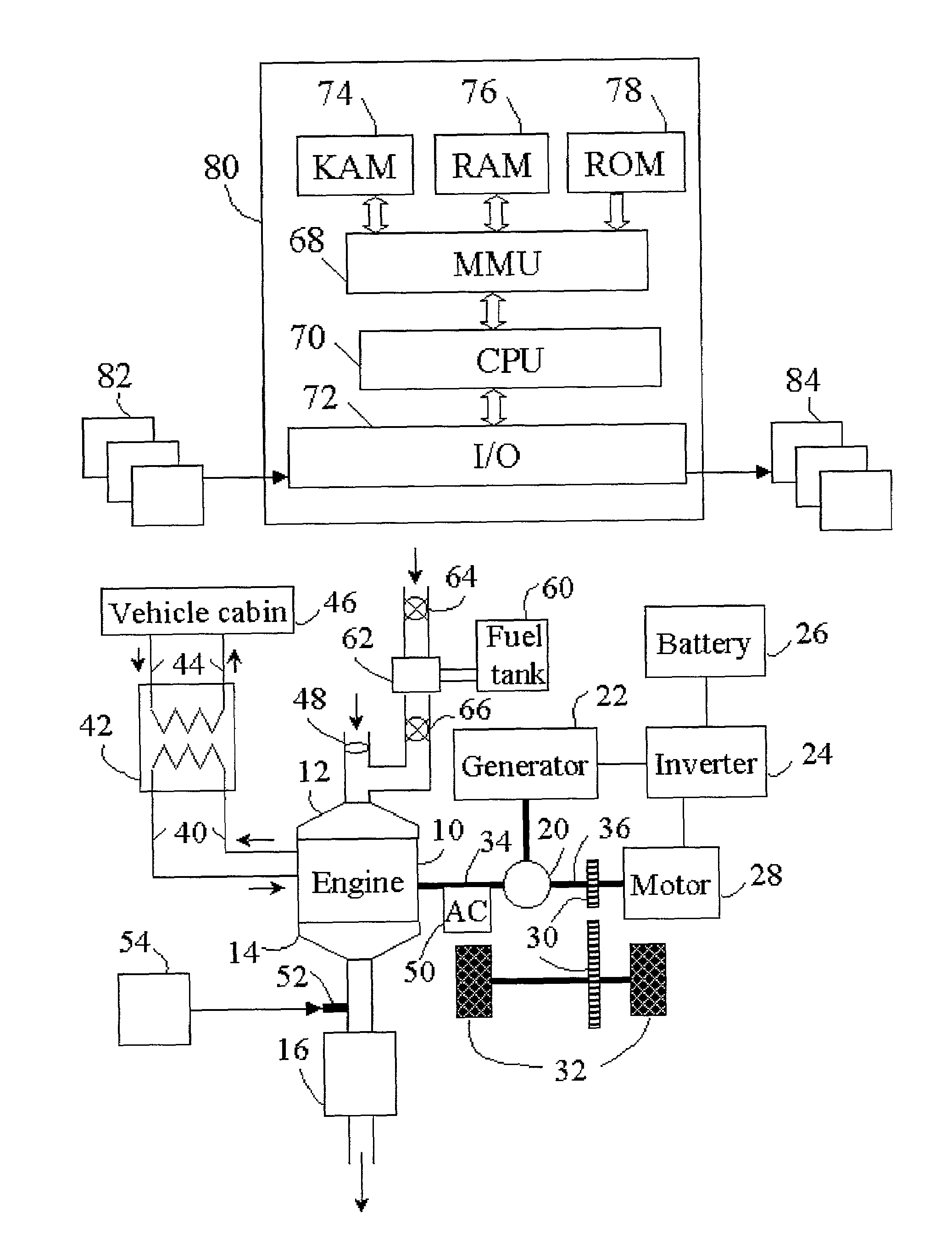
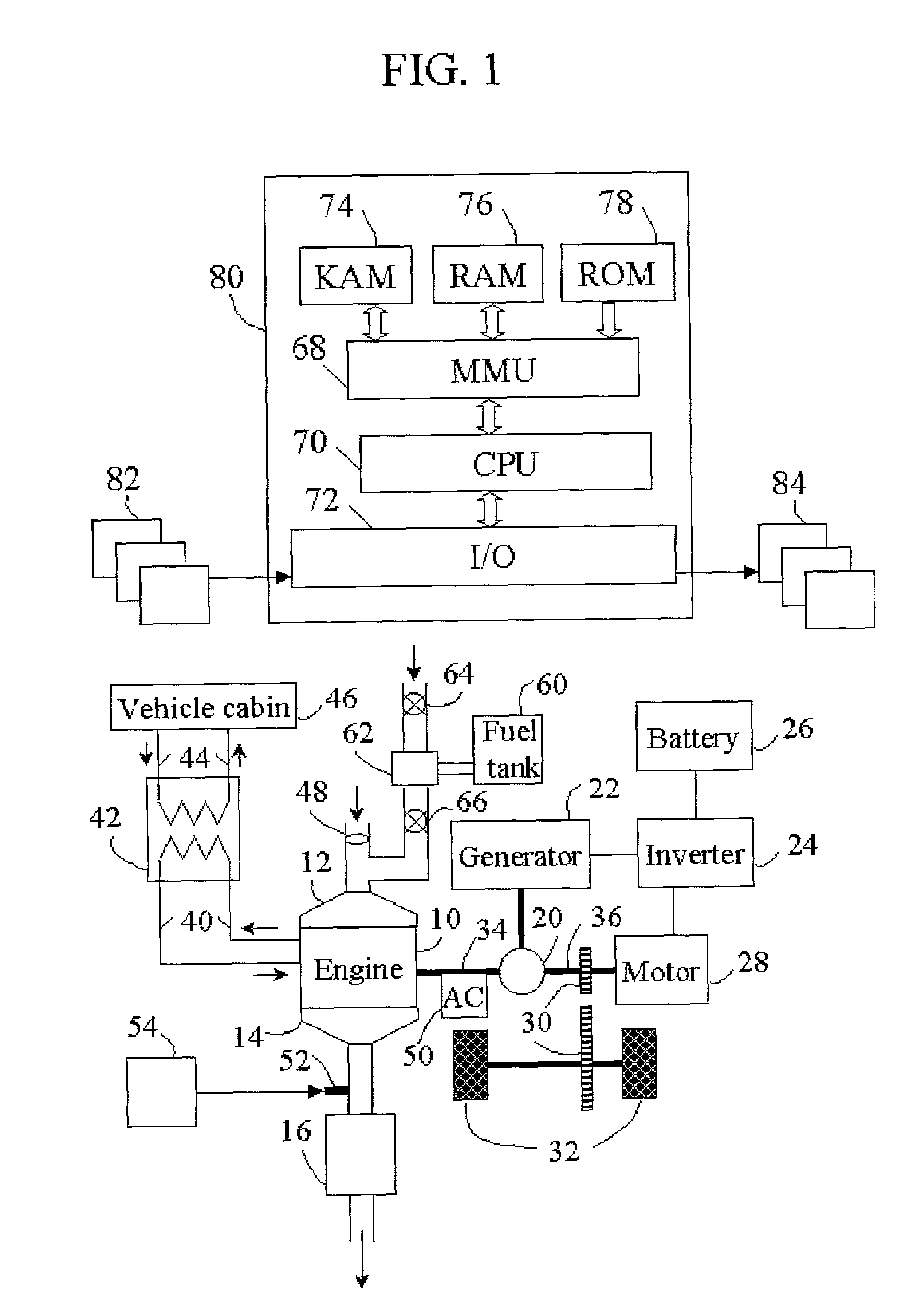
[0019]An example of a hybrid vehicle system is shown in FIG. 1. The hybrid vehicle has an engine 10 and electric motor 28, both of which can provide motive force to driving wheels 32. Power split device 20 is coupled to electric motor 28, generator 22, and engine output shaft 34 of engine 10. Power split device 20 may cause the output of engine 10 to be delivered to output shaft 36 or to generator 22. Output shaft 36 is coupled to the driving wheels 32 via gear set 30. Output shaft 36 may be supplied power by engine 10, electric motor 28, or a combination of the two. Generator 22 is connected to battery 26 via an inverter 24. Power generated by engine 10, which is in excess of that needed at the driving wheels 32, can be supplied to generator 22, which ultimately stores energy in battery 26. Energy can be extracted from battery 26 through inverter 24 and provided to motor 28.

[0020]The hybrid system of FIG. 1, commonly referred to as an electric hybrid, is provided as one example con...


PUM


Abstract

A system and method is disclosed for operating an internal combustion engine disposed in a hybrid vehicle, in which engine operation is selected to provide secondary vehicular functions, such as cabin heating, cabin cooling, and exhaust aftertreatment of exhaust components.

Description

[0001]This application is a continuation of U.S. patent application Ser. No. 09 / 682,240, filed on Aug. 9, 2001, now U.S. Pat. No. 6,421,599, entitled “Control Strategy For An Internal Combustion Engine in a Hybrid Vehicle”, assigned to the assignee of the parent application, and incorporated in its entirety herein by reference.BACKGROUND OF INVENTION[0002]The invention relates to a system and method to operate an internal combustion engine to facilitate the operation of secondary devices, such as emission aftertreatment devices, which depend on the operating condition of the engine to which they are coupled. In the present invention, the internal combustion engine is part of a hybrid vehicle system.[0003]The primary function of an automobile is to transport passengers and cargo. There are, however, secondary vehicular functions including cooling the vehicle cabin, heating the vehicle cabin, and exhaust aftertreatment functions to lower the emission of regulated gaseous components fr...

Claims


Application Information

Patent Timeline
IPC IPC(8): F01N3/20F02B73/00B60H1/32B60K6/08B60K6/10B60K6/12B60K6/445B60W10/06B60W10/30B60W20/00F01N3/023F02D41/02F02D41/08
CPCB60H1/3208B60K6/10B60K6/105B60K6/12B60K6/445B60W10/06B60W10/30F02D41/027F02D41/083B60K6/08B60Y2300/476B60L2240/445B60W20/00B60W2510/0671B60W2510/068B60W2710/0622F01N3/023F01N2570/04F01N2570/14F01N2610/02F01N2610/03F02D2250/18Y02T10/6204Y02T10/6208Y02T10/22Y02T10/6239Y02T10/12Y02T10/62B60W20/15
Inventor LIPPA, ALLAN J.BREHOB, DIANA D.YANG, JIALINXU, LIFENG
Owner FORD GLOBAL TECH LLC
Why Eureka
Try Eureka