Interferometric modulator and display unit

a technology of interferometry and modulator, applied in the field of interferometry modulator and display unit, can solve the problems of chromatic aberration depending on the viewing angle, lower contrast of display methods, impracticality,

Inactive Publication Date: 2006-09-26
SHARP KK
View PDF17 Cites 138 Cited by
  • Summary
  • Abstract
  • Description
  • Claims
  • Application Information

AI Technical Summary

Benefits of technology

[0042]In the interferometric modulator of this invention, the reflectance of light incident from the transparent substrate side is controlled by adjusting the gap length between the optical thin film or stacked film provided on the transparent substrate and the absorber layer. A basic design concept of the interferometric modulator according to the first aspect of the invention is to employ the optical thin film acting as the anti-reflection film (i.e., reflection reducing film) and / or reflection enhancement film most effectively for the wavelength (e.g., 550 nm) in the visible wavelength region. On the other hand, a basic design concept of the interferometric modulator according to the second aspect of the invention is to employ the stacked film capable of achieving the anti-reflection film and / or reflection enhancement film for any wavelength in the visible wavelength region, namely, in the wide band. In either case, the optical thin film or stacked film constructed to become the anti-reflection film when contacted with the absorber layer acts as the reflection enhancement film by forming a predetermined distance of the gap (e.g., air layer) to the absorber layer. Accordingly, the interferometric modulator of the invention provides a higher reflectance and a higher contrast ratio than the conventional interferometric modulator of the iMoD™ method based on the Fabry-Pérot interference. Also, by employing the interferometric modulator of the invention, the reflection type display unit having high brightness and high contrast ratio is produced.

Problems solved by technology

However, these display methods have lower contrast and are impractical.
An electrophoresis method of color particles in a solution, a dichroic rotary particle (twisted ball) method, and a toner display method have been proposed as the display method using other than the liquid crystal, but have not been put to practical use because of the problems with the driving voltage, contrast, response speed, stability and life.
However, since the bright display with the iMoD™ method is “monochrome display” using optical interference, there is a great dependence on the angle of incidence, causing a chromatic aberration depending on the viewing angle.
On the other hand, the white display is limited by a bandwidth (e.g., FWHM) of interference reflection of each color, because each pixel of RGB is realized by additive color mixture, whereby the Y value of the white display is difficult to increase.
Moreover, with this iMoD™ method, a binary display of bright and darkness is made, and a half tone display is only possible by using a spatial dithering (area gradation method) based on the pulse width modulation, resulting in a large load.

Method used


Image

  • Interferometric modulator and display unit
  • Interferometric modulator and display unit
  • Interferometric modulator and display unit

Examples


embodiment 1

(Embodiment 1)

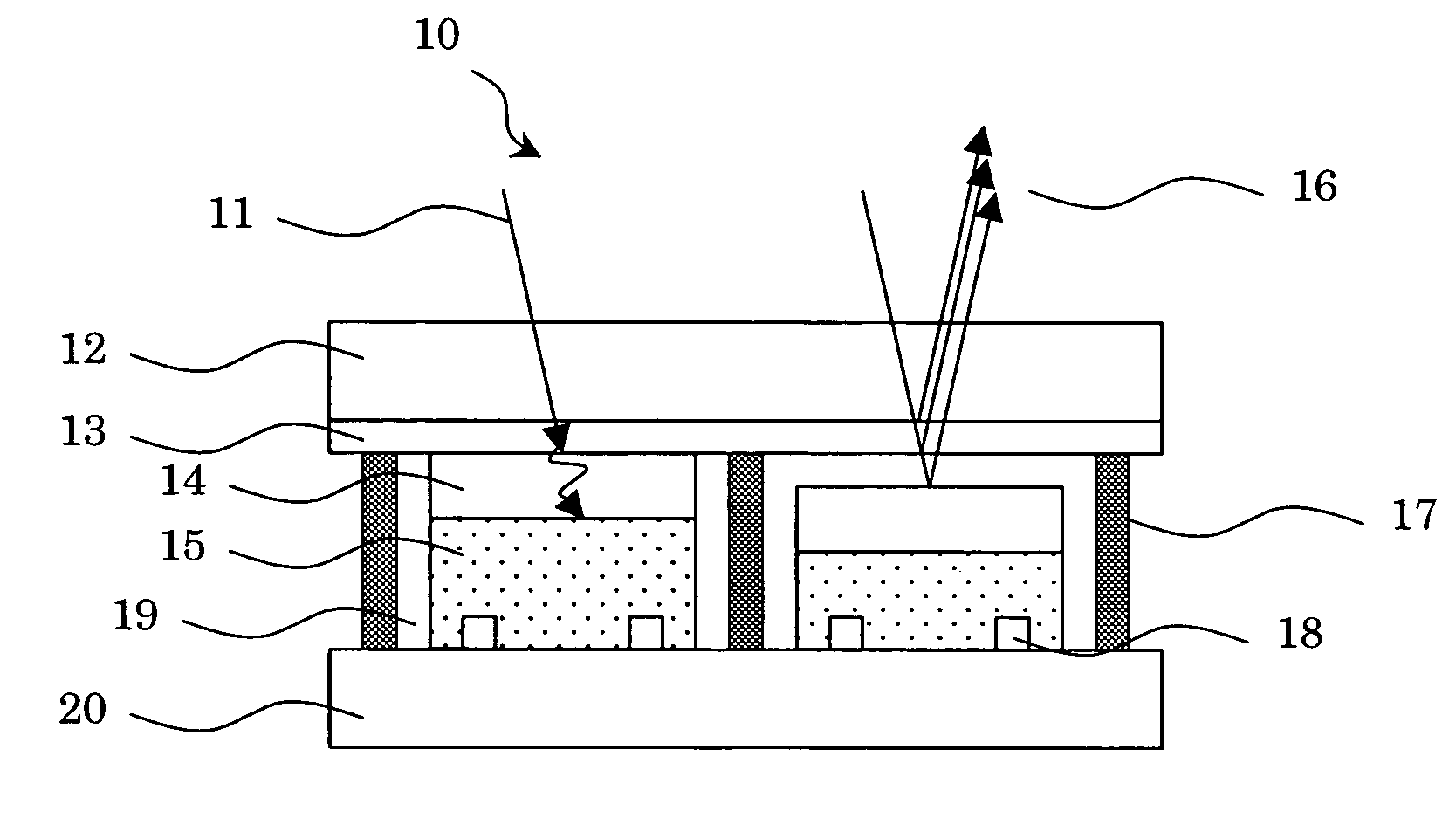
[0074]FIG. 3 is a schematic view showing the configuration of a reflection type display unit 10 according to a first embodiment of the invention. The reflection type display unit 10 has a plurality of interferometric modulators arranged like a matrix, in which each interferometric modulator constitutes a pixel, for example. FIG. 3 shows two pixels of the reflection type display unit, namely, two interferometric modulators, in which the left interferometric modulator is in a black display state (a state with the smallest reflectance) and the right interferometric modulator is in a white display state (a state with the largest reflectance).

[0075]Each of the interferometric modulators making up the reflection type display unit 10 includes a transparent substrate 12, an optical thin film 13 provided on the transparent substrate 12, and an absorber layer 14 having the variable distance of a gap to the optical thin film 13.

[0076]The absorber layer 14 is formed on a driving e...

embodiment 2

(Embodiment 2)

[0122]FIG. 7 is a schematic view showing the configuration of a reflection type display unit 30 according to an embodiment 2 of the first aspect of the invention.

[0123]Each of the interferometric modulators making up the reflection type display unit 30 includes a transparent substrate 32, an optical thin film 33 provided on the transparent substrate 32, and an absorber layer 34 having the variable distance of a gap to the optical thin film 33.

[0124]The absorber layer 34 is formed on a driving element 35 provided on a substrate 40. The substrate 40 and the transparent substrate 32 (herein the optical thin film 33 formed on the transparent substrate 32) are spaced at a predetermined interval and fixed by the spacer walls 37. The spacer walls 37 enclose a medium 39 filling a gap formed between the absorber layer 34 and the optical thin film 33. The piezoelectric element 35 is controlled by one pair of electrodes 38.

[0125]When the absorber layer 34 and the optical thin fil...

embodiment 3

(Embodiment 3)

[0140]FIG. 9 is a schematic view showing the configuration of a reflection type display unit 50 according to an embodiment 3 of the second aspect of the invention.

[0141]Each of the interferometric modulators making up the reflection type display unit 50 includes a transparent substrate 52, a stacked film 53 provided on the transparent substrate 52, and an absorber layer 54 having the variable distance of a gap to the stacked film 53. The stacked film 53 has three or more transparent thin film layers, the complex indexes of refraction of two adjacent transparent thin film layers being mutually different. The stacked film 53 as shown here has an alternate stacked film in which a first transparent thin film layer 53a having a larger refractive index and a second transparent thin film layer 53b having a smaller refractive index are alternately stacked, and a third transparent thin film layer 53c opposed to the absorber layer 54 provided on the alternate stacked film. Emplo...


PUM


Abstract

The interferometric modulator of the invention includes a transparent substrate (refractive index: n0) 12, an optical thin film (complex index of refraction: N1=n1−i·k1) 13 provided on the transparent substrate 12, and an absorber layer (complex index of refraction: Ns=ns−i·ks) 14 opposed to the optical thin film 13, the distance of a gap to the optical thin film 13 being variable, wherein the relation n1>n0, k1≅0 and ns>n0 is satisfied.

Description

BACKGROUND OF THE INVENTION[0001]1. Field of the Invention[0002]The present invention relates to an interferometric modulator and a display unit with the interferometric modulator, and more particularly to an interferometric modulator that is suitably employed for a reflection type display unit.[0003]2. Description of the Related Art[0004]Generally, the reflection type display unit employs the ambient light, and is particularly useful for the mobile purposes.[0005]Currently, the typical reflection type display units are employed in a TN (Twisted Nematic) mode or an STN (Super-Twisted Nematic) mode using the birefringence or optical rotatory power of the liquid crystal.[0006]However, in these display modes, it is required to use a polarizing plate, in which an optical loss by the polarizing plate is as large as about 60%, so that the display is darker.[0007]On the other hand, a guest-host method in which dichroic dye is added to liquid crystal and a transmitting / scattering method rep...

Claims


Application Information

Patent Timeline
Patent Type & Authority Patents(United States)
IPC IPC(8): G02B1/10G02B26/08G02B5/26G02B5/28G02B26/00
CPCG02B26/001
Inventor TAGUCHI, TOKIOUEKI, SHUNTSUDA, KAZUHIKO
Owner SHARP KK
Why Eureka
Try Eureka