Cooling device for electronic element producing concentrated heat and electronic device

a technology of electronic elements and cooling devices, which is applied in the direction of electrical equipment, lighting and heating equipment, and domestic cooling equipment, etc., can solve the problems of cpu malfunction, affecting the operation temperature affecting the efficiency of the cooling system, so as to achieve more effective heat radiation

Inactive Publication Date: 2006-09-26
KK TOSHIBA
View PDF29 Cites 26 Cited by
  • Summary
  • Abstract
  • Description
  • Claims
  • Application Information

AI Technical Summary

Benefits of technology

[0014]The second chassis which is provided separately from the first chassis housing the electronic element can be employed to radiate the heat so that more effective heat radiation can be achieved as well as the active heat transport unit keeps the cooling medium flowing into the electronic element in relatively low temperature.

Problems solved by technology

However, when heat producing rate of the CPU got larger, an operation temperature of the cooling system would get higher because of a limit of heat radiation efficiency of the heat radiation unit or a limit of heat transport efficiency of the heat pipe or the flexible tube.
Such a case gives rise to a higher operation temperature of the CPU and, therefore, leads to a concern about a shorter lifetime or a malfunction of the CPU.

Method used


Image

  • Cooling device for electronic element producing concentrated heat and electronic device
  • Cooling device for electronic element producing concentrated heat and electronic device
  • Cooling device for electronic element producing concentrated heat and electronic device

Examples


first embodiment

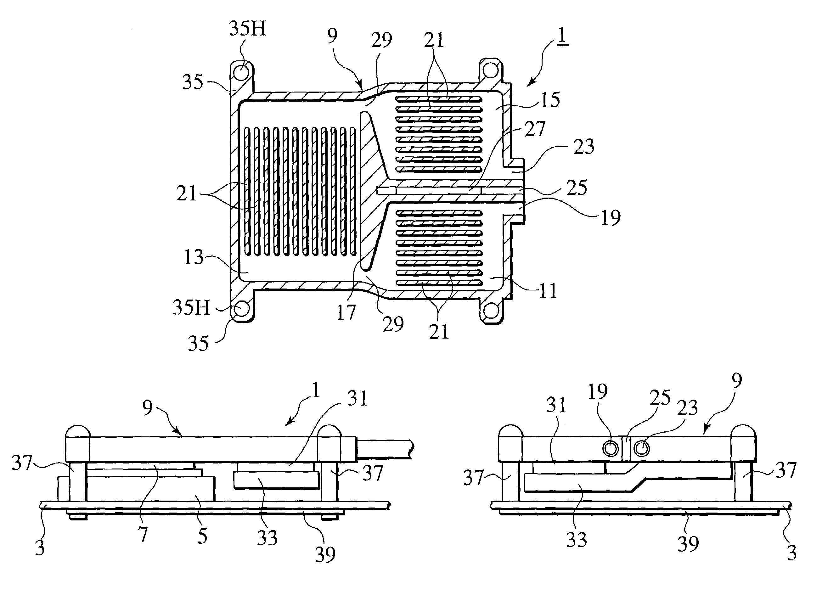
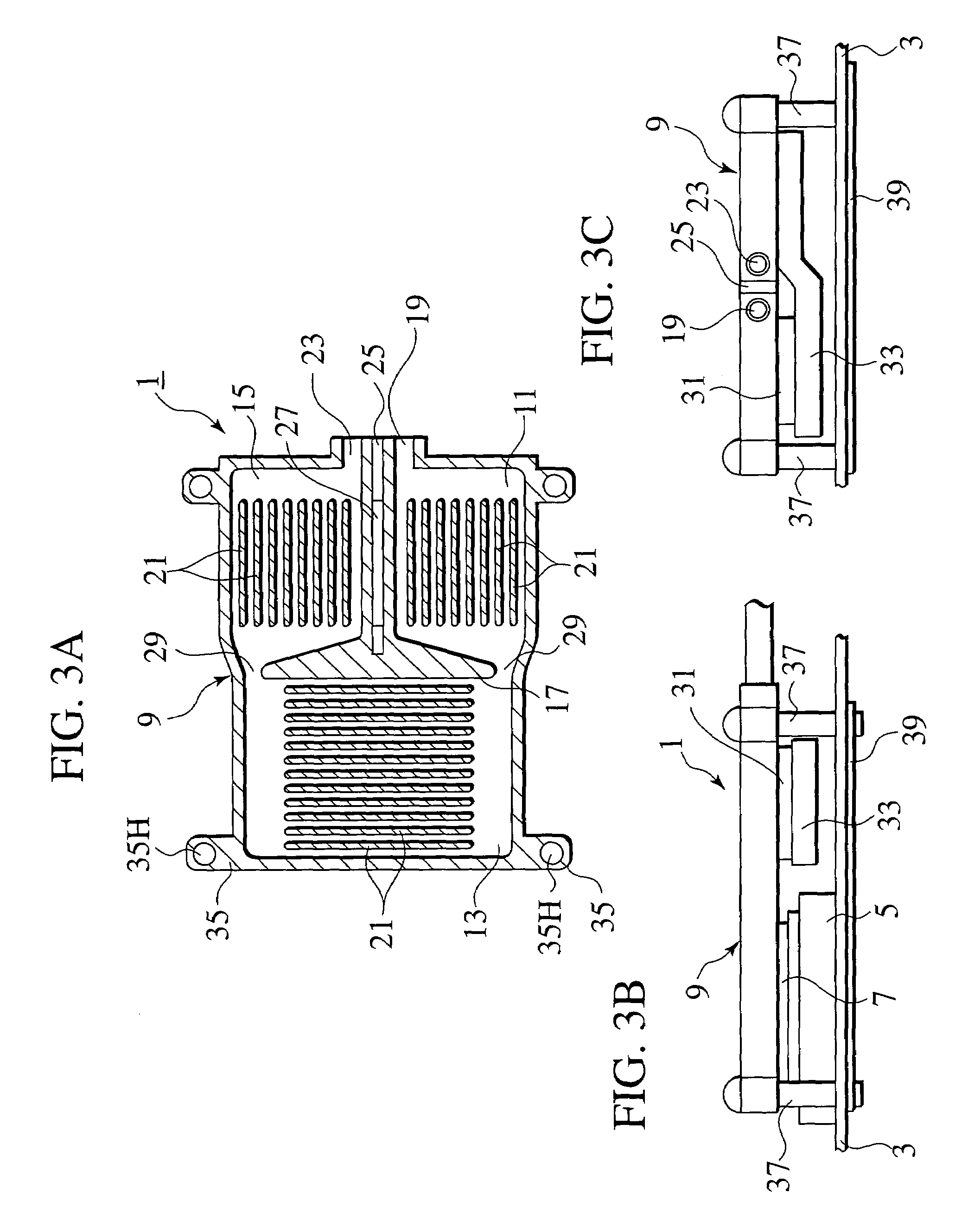
[0033]the present invention will be described hereinafter with reference to FIGS. 3A–3C. In the following description, a CPU 7 is exemplified as an electronic element and a Peltier element 31 is exemplified as an active heat transport unit, however, the present invention may be enabled with any proper elements or devices other than the CPU 7 and the Peltier element 31.

[0034]A cooling device 1 according to the first embodiment is basically composed of a casing 9 which has an inflow port 19 and an outflow port 23 and is made in a watertight manner, the Peltier element 31 and a heat transfer member 33, both of which are connected with a lower side thereof. The cooling device 1 is installed to a substrate 3 of an electronic device so as to be thermally connected with the CPU 7 electrically connected with a socket 5 on the substrate 3.

[0035]Inside of the casing 9, as the sectional view thereof shown in FIG. 3A, an element cooling chamber 13, a coolant cooling chamber 11 and a coolant hea...

second embodiment

[0049]The second embodiment increases a degree of a design freedom of an electronic device interior because the element cooling chamber can be disposed independently of the coolant cooling chamber 11 and the coolant heating chamber 15.

[0050]A third embodiment of the present invention will be described hereinafter with reference to FIGS. 5A and 5B. Rear surfaces of the coolant cooling chamber 11 and the coolant heating chamber 15 are directed with each other and the Peltier element 31 is put therebetween. The heat transfer member 33 bridged between the Peltier element 31 and the coolant heating chamber 15 is omitted in the third embodiment. The third embodiment can be more simply constituted and heat transfer between the Peltier element 31 and the coolant heating chamber 15 comes to be more effective.

[0051]A fourth embodiment will be described hereinafter with reference to FIG. 6. In the fourth embodiment, air is employed to the cooling medium. A fin base 47B provided with a pluralit...

third embodiment

[0054]FIG. 7 is a schematic drawing of a notebook PC 56 as an example of the electronic device to which the cooling device of the second or third embodiment is applied.

[0055]The notebook PC 56 is provided with an element cooling area 67 corresponding to the element cooling chamber. The coolant cooling chamber 11 and the coolant heating chamber 15 are housed in an auxiliary heat radiation unit 69. The auxiliary heat radiation unit 69 is housed in a main chassis 103 of the notebook PC 56 and is connected with a heat radiation unit 41 housed in a sub-chassis 105 via a pipe line 70. The main chassis 103 further houses a pump 43 connected with the pipe line 70 so that a cooling medium circuit is constituted and the cooling medium is circulated therein.

[0056]The element cooling area 67 is provided with an inlet port 67A and an outlet port 67B for the cooling medium and is further provided with a plurality of fins 67C therein as shown in FIG. 8. The element cooling area 67 is thermally con...


PUM


Abstract

A cooling device is applied to cooling an electronic element producing concentrated heat in a case where the electronic element is housed in a portable electronic device such as a notebook PC. The cooling device is provided with an active heat transport element provided with a heat intake portion and a heat outlet portion, which conducts heat from the heat intake portion to the heat outlet portion, a first flow channel disposed upstream of the electronic element in flow of the cooling medium, a second flow channel disposed downstream of the electronic element in the flow of the cooling medium. The heat is by-passed by means of the active heat transport element so that the electronic element is exposed to flow of the cooled cooling medium and effectively cooled thereby.

Description

CROSS-REFERENCE TO RELATED APPLICATIONS[0001]This application is based upon and claims the benefit of priority from the prior Japanese Patent Application No. 2002-204490 (filed Jul. 12, 2002); the entire contents of which are incorporated herein by reference.BACKGROUND OF THE INVENTION[0002]1. Field of the Invention[0003]The present invention relates to a cooling device for effectively cooling an electronic elements producing concentrated heat, such as a CPU, which is employed to a portable electronic device having few space to conduct and radiate the concentrated heat, such as a notebook PC, and a portable electronic device to which the cooling device is installed with an effective configuration.[0004]2. Description of the Related Art[0005]As technology has increased a capacity of electronic elements, it has been found that the amount of produced heat has increased significantly. Though the amount of the heat is in a range of several Watts to several tens Watts, it is far from easy...

Claims


Application Information

Patent Timeline
Patent Type & Authority Patents(United States)
IPC IPC(8): H05K7/20H01L23/38H01L23/36H01L23/473
CPCH05K7/20254
Inventor HISANO, KATSUMITAKAMATSU, TOMONAOIWASAKI, HIDEO
Owner KK TOSHIBA
Why Eureka
Try Eureka