
Noise canceling method and apparatus

a technology of noise cancellation and noise reduction, applied in the field of noise cancellation methods and apparatuses, can solve the problems of inability to carry out communication, limited application in practice, and inability to use fast data communication using a power-line carrier

Inactive Publication Date: 2006-09-26
FUJITSU LTD
View PDF14 Cites 19 Cited by
  • Summary
  • Abstract
  • Description
  • Claims
  • Application Information

AI Technical Summary

Benefits of technology

[0022]It is a general object of the present invention to provide an improved and useful noise canceling method and apparatus in which the above-mentioned problems are eliminated.
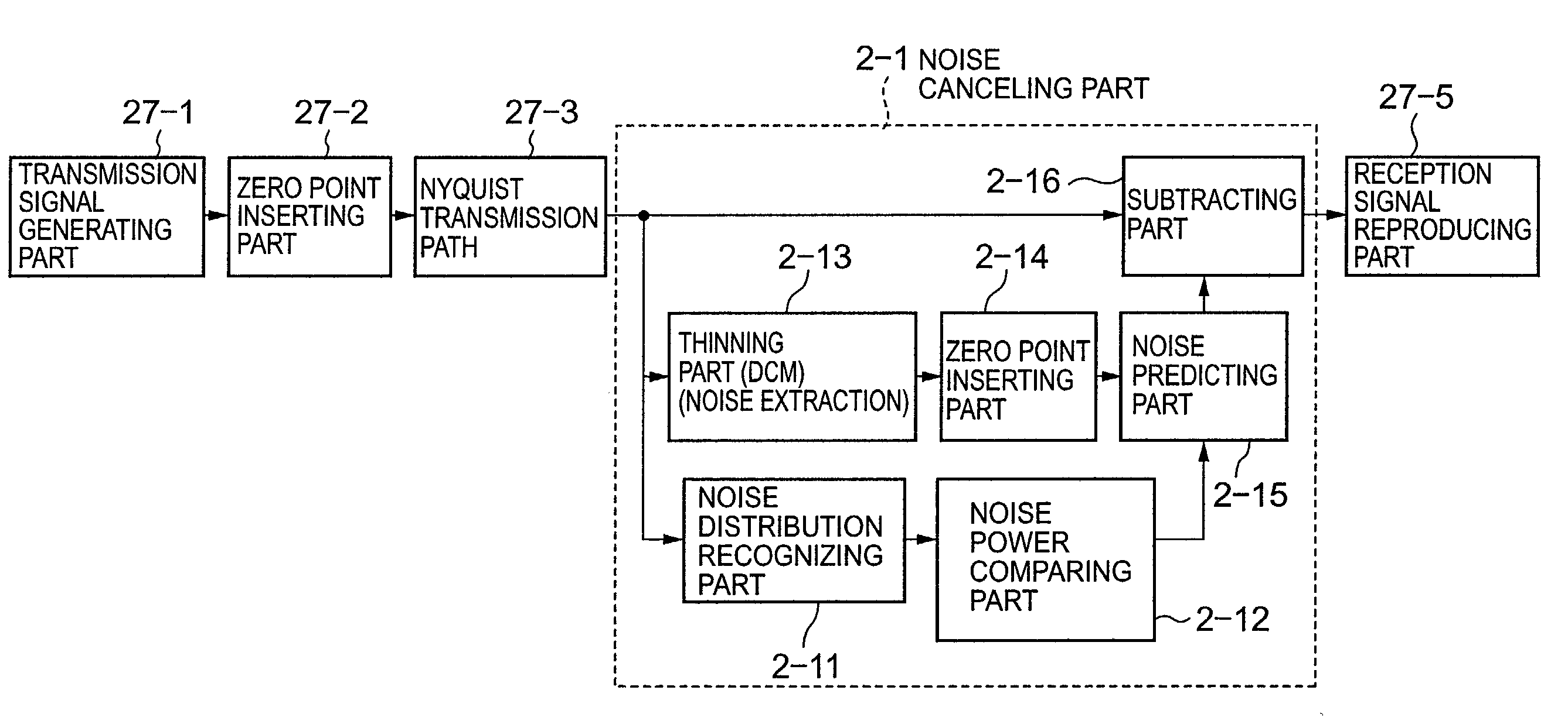
[0023]A more specific object of the present invention is to provide a noise canceling method and apparatus which can achieve a fast communication by improving an S / N value by adaptively canceling a noise with respect to a frequency or band having a large noise by selecting noise canceling band in accordance with a condition of noise being generated.
[0031]According to the present invention, a noise canceling band can be selected in accordance with a state of noise actually generated in scattered bands so as to adaptively applies noise cancellation to the bands having a large noise. Thereby, an S / N ratio is improved and a fast communication can be achieved.
[0032]Additionally, an accuracy of recognition of a noise distribution can be improved by combining a low-band noise cancellation and a noise cancellation according to the recognition of a noise distribution, thereby improving an accuracy of entire noise cancellation.
[0033]Further, a noise scattering on a high-band side can be effectively canceled by notifying the transmission side of a noise distribution recognized by the reception side so as to change an order of channels on the transmission side based on the noise distribution that noises are gathered to a low band side when the order of the channels is restored to an original order by the reception side.

Problems solved by technology

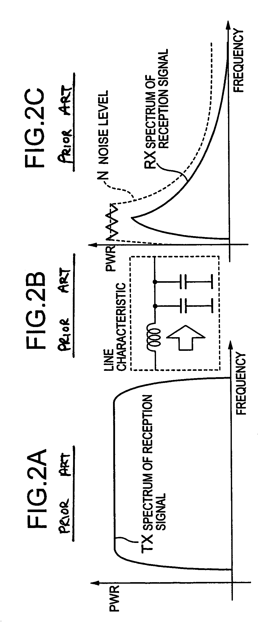
On the other hand, although the low-frequency band component does not attenuate as much as the high-frequency band component, the low-frequency band component is also buried in a large noise N as shown in FIG. 2C since an extremely large amount of random noise (white noise) is emitted from electric appliances using a switching power supply or an inverter device.
Accordingly, a fast data communication using a power-line carrier has not been put into practical use, and there has been a demand for finding a solution for a long time.
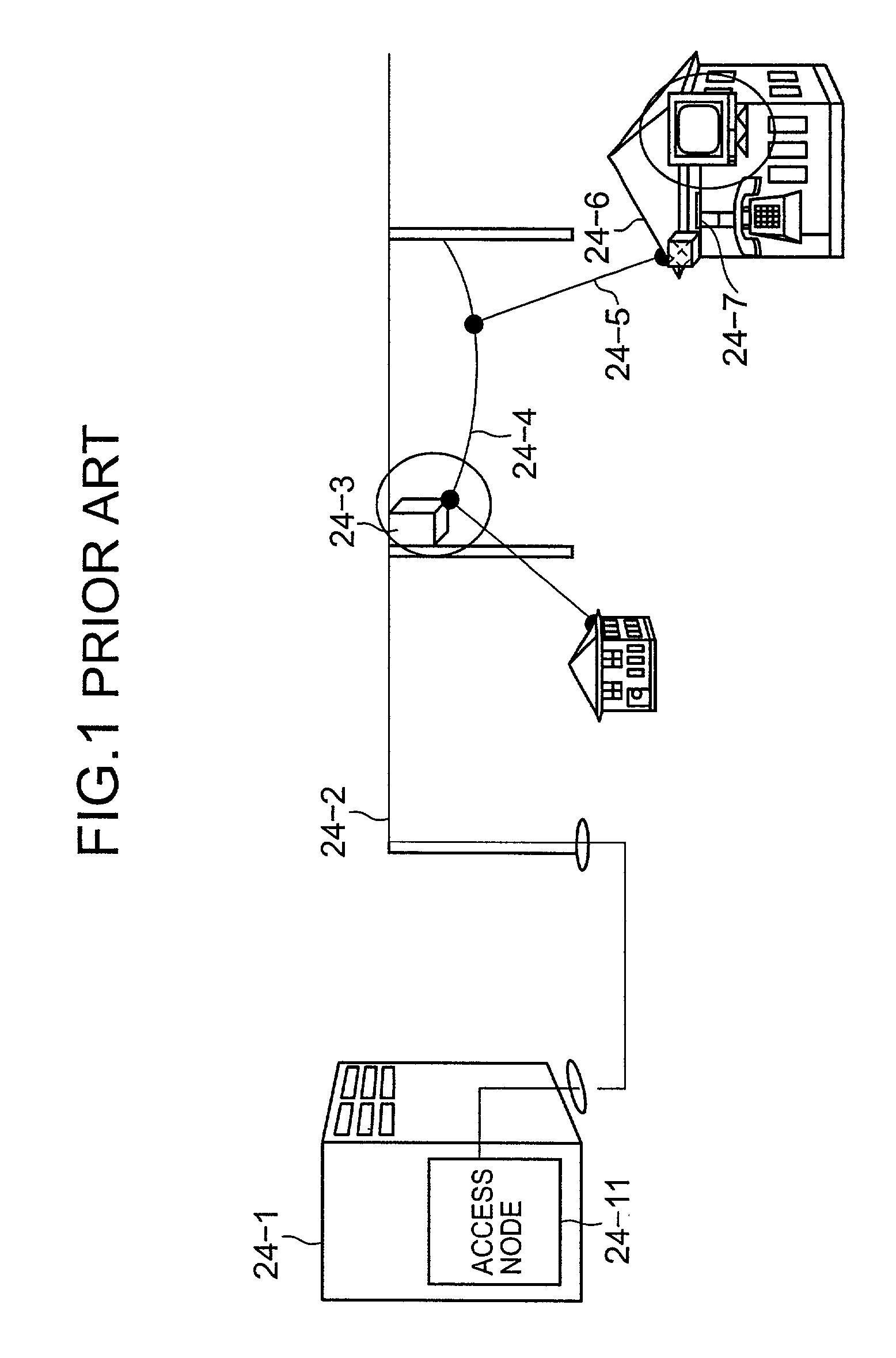
However, a limited application has been made in practice, such as an application related to a low data transmission speed of less than 1200 bps since the power line has an extremely large noise level.
The transmission rate is 100 kbps at maximum, and it becomes incapable of carrying out communication in worst case.
However, the number of switching power source and inverter devices in home electric appliances, which are main source of noises, tends to increase, and it has become further difficult to avoid an attenuation of high-band signals due to the capacitive load.
Accordingly, the power-line carrier communication can be put in a practical in a low-speed communication, but it is impossible to achieve the power-line carrier communication at a high rate as high as a few Mbps.
In the future, the number of switching power source and inverter devices in home electric appliances will be increased, and it will become further difficult to avoid an attenuation of high-band signals due to the capacitive load.
Under such circumstances, the communication being carried out while avoiding noises in the prior art is not sufficient.
However, there is a case in which a noise having a comb-like spectrum distributed in a wide band is generated due to a noise of use of an inverter provided equipped in home electric appliances or a frequent band noise generated by radio interference by AM broadcasting carrier.
In such as case, if only a noise within a predetermined range is cancelled, the S / N value deteriorates which generates frequent reception errors since noises in ranges other than the noise canceling band remain uncanceled.

Method used


Image

  • Noise canceling method and apparatus
  • Noise canceling method and apparatus
  • Noise canceling method and apparatus

Examples


Embodiment Construction

[0071]Prior to a description of an embodiment of the present invention, a description will be given of an outline of the prior invention of canceling a noise in which a band for canceling a noise is a fixed range.

[0072]As shown in FIG. 3A, an S / N ratio is maintained to be a minus value even if a low-frequency range (noise component N1, signal component S1) is cut off so as to transmit data using a high-frequency range.

[0073]However, the S / N value can be turned to a plus value by extracting a relatively high-level reception signal S buried in noises in the low band as shown in FIG. 3B by canceling the dominant noise component N1 in the low band with respect to a noise which is a colored noise in a macroscopic view such as a low-band enhancement type noise as shown in FIG. 3A. The prior invention predicts by interpolation a noise component from the reception signal containing a specific signal having specific time position, amplitude and phase to carry out a noise cancellation so as t...


PUM


Abstract

A canceling method and apparatus can achieve a fast communication by improving an S / N value by adaptively canceling a noise with respect to a frequency or band having a large noise by selecting noise canceling band in accordance with a condition of noise being generated. A reception signal contains a specific signal having a specified time position, amplitude and phase. A noise distribution of the specific signal is recognized so as to predict a noise by extracting a frequency band having a larger noise component from a pair of frequencies generated by the insertion of the specific signal. An original transmission signal is reproduced by canceling the predicted noise from the reception signal.

Description

BACKGROUND OF THE INVENTION[0001]1. Field of the Invention[0002]The present invention generally relates to noise canceling methods and apparatuses and, more particularly, to a noise canceling method and apparatus for accurately extracting signals buried in noises in communications under a large noise circumstance.[0003]Such a noise canceling method and apparatus is preferably applicable to apparatuses over various fields as mentioned below.[0004]a modem for power-line carrier communication for achieving fast data transmission using an electric line such as a power line having many noises;[0005]a CATV modem, an ADSL modem, a VDSL modem, a radio LAN of 2.4 GHz band, other radio transmission fields and an optical transmission field;[0006]a magnetic disk drive units or optical disk drive unit for achieving achieve high-density recording by enabling an extraction of signals which tend to be buried in noise under a high-speed operation;[0007]a semiconductor device using a fast multi-value...

Claims


Application Information

Patent Timeline
Patent Type & Authority Patents(United States)
IPC IPC(8): H03D1/04H03K5/01H04B1/10H04L25/08G10L15/20G10L21/0208H04B1/12H04B3/54H04B15/02H04J11/00H04L27/00H04L27/26H04L27/34H04R3/02
CPCH04B1/1036H04B1/12H04L27/2647H04B1/123H04B2203/5425
Inventor KAKU, TAKASHIOKITA, RYOJI
Owner FUJITSU LTD
Learn More