Method and arrangement of controlling of percussive drilling based on the stress level determined from the measured feed rate

a percussive drilling and stress level technology, applied in the field of rock drills, can solve the problems of premature fatigue failure of drilling tools, rock breaks, worn threaded joints between drill rods,

Inactive Publication Date: 2006-10-03
SANDVIK TAMROCK
View PDF12 Cites 10 Cited by
  • Summary
  • Abstract
  • Description
  • Claims
  • Application Information

AI Technical Summary

Benefits of technology

[0005]An object of the present invention is to provide a no

Problems solved by technology

Rock breaks, however, mainly by the effect of an impact.
If drilling is continued into soft rock with excessive impact energy it generally results in worn threaded joints between the drill rods and/or premature fatigue failures of the drilling tool.
In general, the method that is currently used for drilling control, a so-called feed-impact-fo

Method used


Image

  • Method and arrangement of controlling of percussive drilling based on the stress level determined from the measured feed rate
  • Method and arrangement of controlling of percussive drilling based on the stress level determined from the measured feed rate
  • Method and arrangement of controlling of percussive drilling based on the stress level determined from the measured feed rate

Examples


example

[0032]FIG. 6 shows schematically, in continuous lines, the highest allowed penetration rates NPRmax in one drilling tool at different tensile stress levels σv. The broken lines are auxiliary lines describing the penetration resistance Kl of the rock to be drilled, which help in perceiving the penetration rates NPR with different penetration resistances Kl of the rock to be drilled and different impact pressures. Initially, the drilling takes place at an operating point A, where the impact pressure is 220 bar and the penetration resistance of the rock is about 300 kN / mm. The highest allowed tensile stress level σvmax set by the drilling machine operator is 140 MPa. The drilling penetration rate at the operating point A is 3.1 m / min, so the penetration rate is lower than the highest allowed penetration rate NPRmax=3.5 m / min corresponding to said impact pressure. As the drilling proceeds, the rock suddenly becomes softer to the penetration resistance value Kl=200 kN / mm, which refers to...


PUM

PropertyMeasurementUnit
Lengthaaaaaaaaaa
Pressureaaaaaaaaaa
Feed rateaaaaaaaaaa

Abstract

The rock drill apparatus (1) comprises a rock drill machine (6) provided with a percussion device (4), a feed device (9) and a tool (7), the tool (7) end comprising a bit (8) for breaking rock. The tool (7) is arranged to transmit impact energy generated by the percussion device (4) as a compression stress wave to the bit. The feed device (9) is arranged to thrust the tool (7) and the bit (8) against the rock to be drilled, whereby on drilling at least part of the compression stress wave generated by the percussion device (4) to the tool (7) reflects from the rock to be drilled back to the tool (7) as tensile stress, and impact energy of the percussion device (4) is adjusted on the basis of the level of tensile stress (σv) reflecting from the rock.

Description

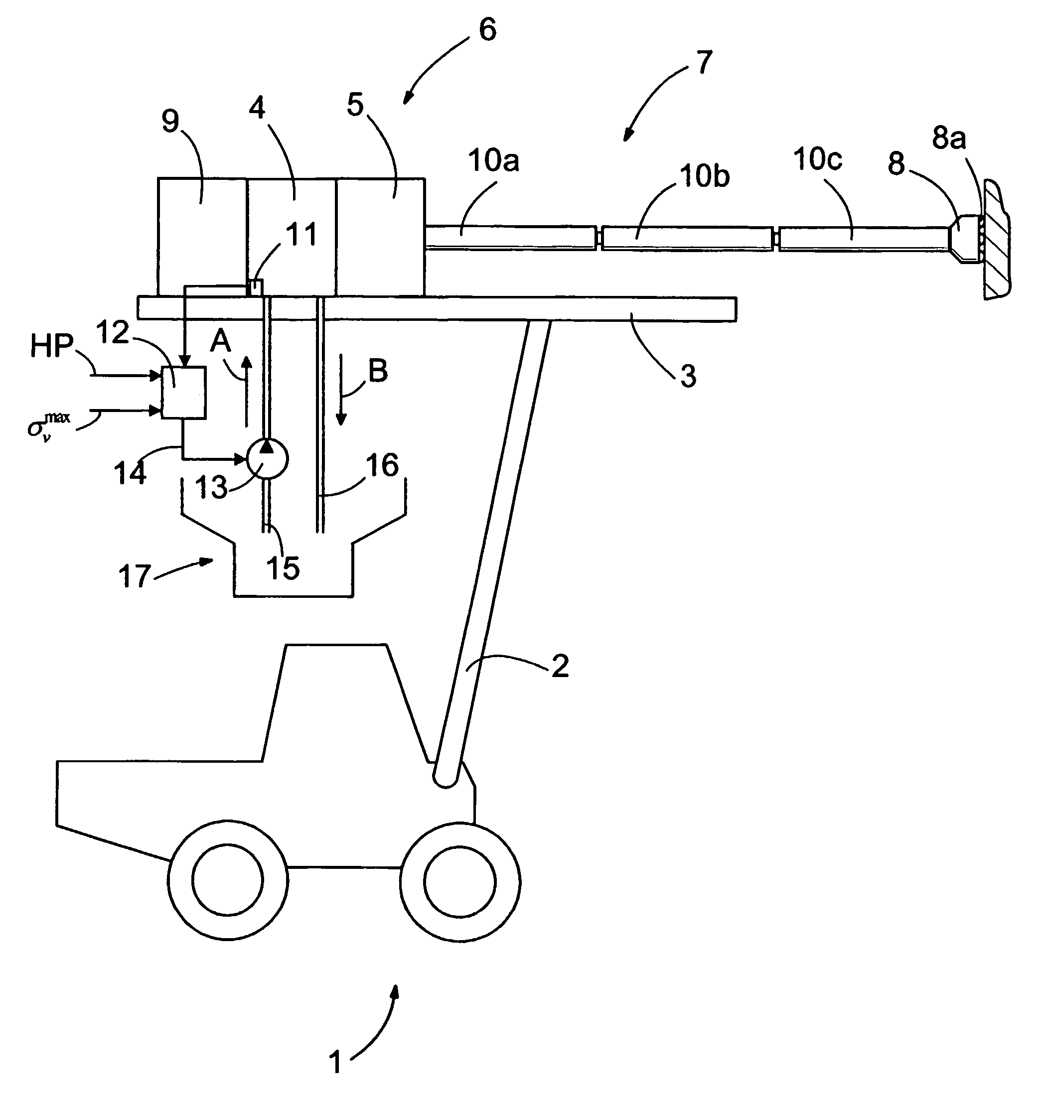
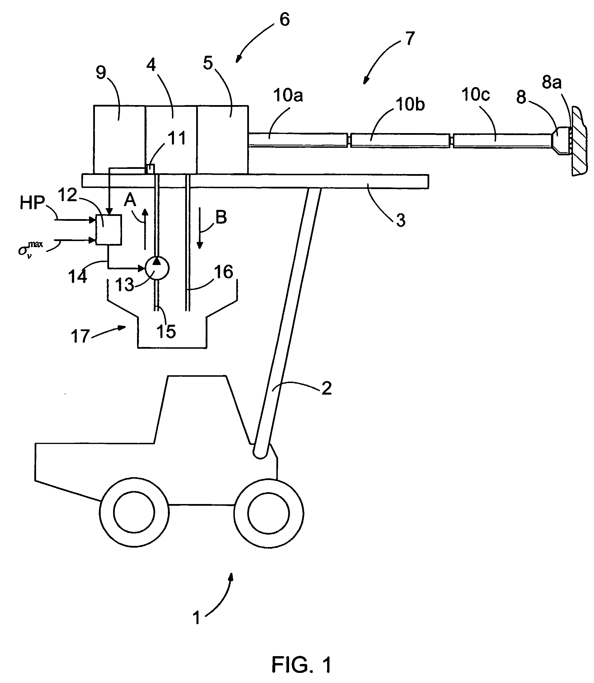
FIELD OF THE INVENTION[0001]The invention relates to a method in connection with a rock drill apparatus, which rock drill apparatus comprises a rock drill machine provided with a percussion device, a feed device and a tool, the tool end comprising a bit for breaking rock, and the tool being arranged to transmit impact energy generated by the percussion device as a compression stress wave to the bit and the feed device being arranged to thrust the tool and the bit against the rock to be drilled, whereby on drilling at least part of the compression stress wave generated by the percussion device to the tool reflects from the rock to be drilled back to the tool as tensile stress.[0002]The invention further relates to an arrangement in connection with a rock drill apparatus, which rock drill apparatus comprises a rock drill machine provided with a percussion device, a feed device and a tool, the tool end comprising a bit for breaking rock, and the tool being arranged to transmit impact e...

Claims


Application Information

Patent Timeline
IPC IPC(8): B25D9/26E21B7/02E21B44/00
CPCE21B44/00
Inventor KESKINIVA, MARKKU
Owner SANDVIK TAMROCK
Why Eureka
Try Eureka