Chemical mechanical planarization equipment, wafer transfer method, and wafer planarization unit

a mechanical and chemical technology, applied in the field of semiconductor equipment, can solve the problems of high production cost, limited and expensive factory space, complex technological process, etc., and achieve the effect of ensuring process stability, simplifying the original complex structure for processing and loading wafers, and small footprin

Pending Publication Date: 2021-08-26
HANGZHOU ZHONGGUI ELECTRONICS TECH CO LTD
View PDF14 Cites 0 Cited by
  • Summary
  • Abstract
  • Description
  • Claims
  • Application Information

AI Technical Summary

Benefits of technology

[0060]Compared with the polishing structure of cross turret mechanism, the advantages of the present invention include:
[0061]1. The independent functional structure and processing area contained in the unit guarantee the stability of the process, and because of the modular design adopted by the unit, the number of CMP groups can be freely defined by customers according to their needs to meet different processing requirements.
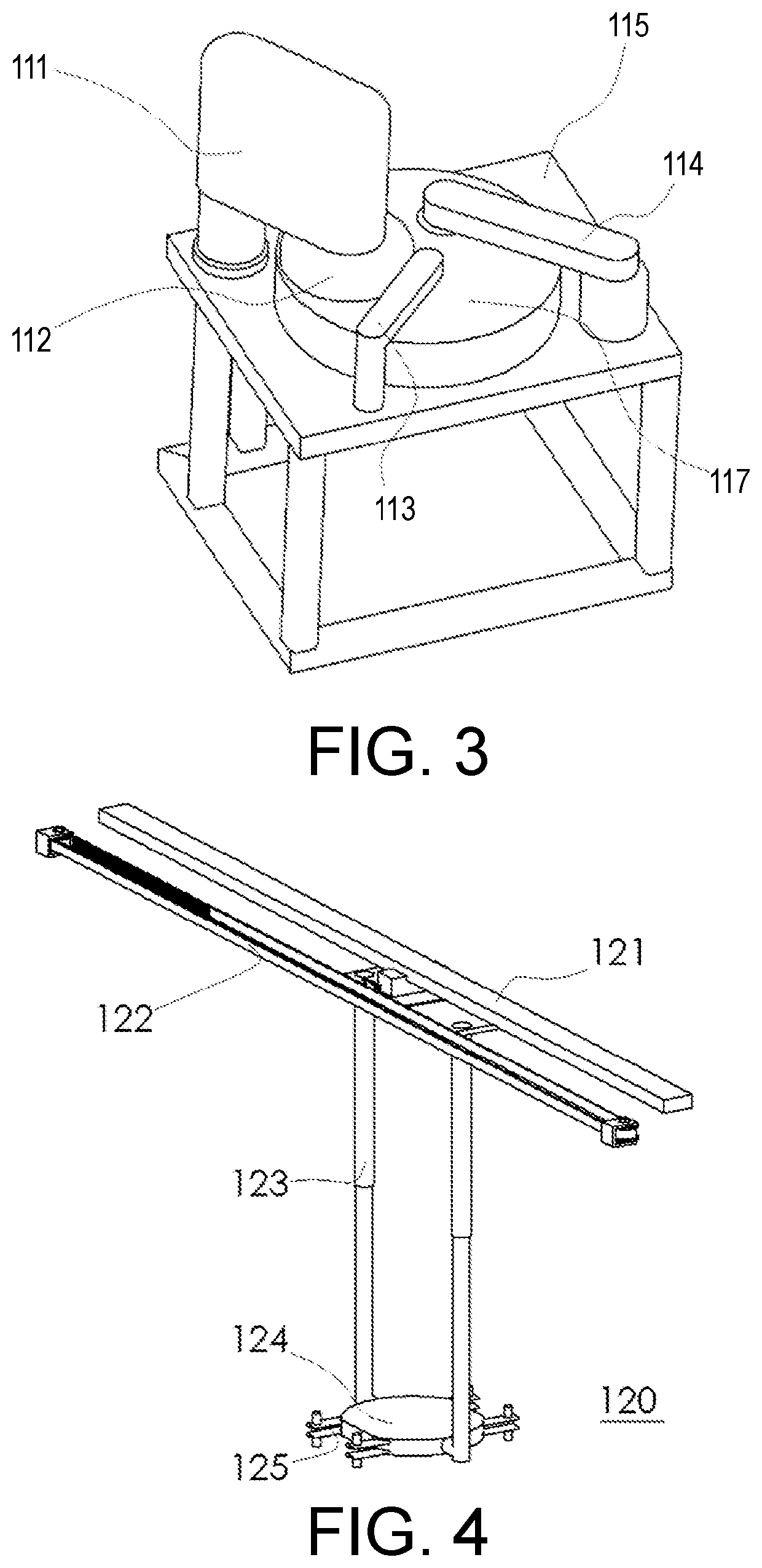
[0062]2. When the internal mechanism is working, the external wafer loading mechanism can be operated independently, and the problem of processing efficiency affected by production suspension due to wafer loading is properly addressed. The existence of a swing arm not only satisfies the original requirements of polishing and loading and unloading wafers, but also simplifies the original complex structure for processing and loading wafers with the cross turret and linear motion.
[0063]3. The wafer loading and unloading device is separated from the internal processing area and an automatic sliding door protection isolation is provided in the middle to prevent secondary contamination to the processed wafers to be cleaned by the liquid in the processing area.
[0064]4. Due to the small footprint of the optimized structure, the output rate per square meter of the purification workshop is greatly increased. If, during group operation, one of the unit modules fails and is being maintained, other units in the CMP group do not need to stop operation.
[0065]5. The cables of related electrical components on the swing arm have the torsion angle less than 180 degrees, half of the previous structural torsion angle, helps to reduce the accident rate of cables due to torsional fatigue.

Problems solved by technology

Clearly, the disadvantage of such technical layout is the complicated technological process, since a transfer station needs to use a shared rotatable device to load and unload the three polishing units.
This layout utilizing the linear arrangement of polishing units has the disadvantage that each polishing unit is equipped with two transfer stations, but the polishing unit only loads and unloads wafers directly from one of them during the polishing process, and the wafer transfer efficiency needs to be improved.
With the popularization and promotion of mobile technology and smart technology, the demand for microchips in chip industry continues to grow, therefore the wafer foundries with limited and highly expensive factory space require higher and higher production capacity.
The disadvantages of the above-mentioned equipment are the relatively large mechanism in size and the complicated structure.
Since the cross turret needs to rotate frequently in a large angle range, the data line of the sensor disposed on the cross turret may rotate with a large angle, easily affecting the measurement stability of the sensor.
If one of the parts of the equipment needs to be repaired, it is required to shut down the whole machine, greatly reducing the utilization rate of the equipment and even resulting in poor process stability during wafer processing.

Method used


Image

  • Chemical mechanical planarization equipment, wafer transfer method, and wafer planarization unit
  • Chemical mechanical planarization equipment, wafer transfer method, and wafer planarization unit
  • Chemical mechanical planarization equipment, wafer transfer method, and wafer planarization unit

Examples


embodiment 1

[0119] As shown in FIG. 10, the driving mechanism of polishing swing arm 3 is positioned above the polishing platform 9. For the driving mechanism, the rotor of motor 20 is connected to the decelerating mechanism 12, and the stator of motor 20 is connected to the cover of the decelerating mechanism 12. The cover of the decelerating mechanism 12 is connected to the polishing swing arm 3 through the decelerating mechanism flange 13. On side of the polishing swing arm 3 is equipped with a polishing head 7, and the other side contains a top bearing 18 at the upper end and a lower bearing 16 at the lower end to ensure the rotation accuracy of swing arm 3. The inner and outer ring of top bearing 18 are connected to the fixed shaft 22 and the polishing swing arm 3 through its own flange screw hole. The axial movement of lower bearing 16 is prevented by the inner ring nut 15 of bearing and the shaft shoulder of polishing swing arm 3. The rotor of motor 20 is connected to the decelerating me...

embodiment 2

[0121] As shown in FIG. 11, the drive mechanism of polishing swing arm 3 is placed under the polishing platform 9. The connection relationship of the drive mechanism is as follows: the cover of the motor 20 is connected to the cover of decelerating mechanism 12 with screws, the rotation shaft of motor 20 is transmitted to the decelerating mechanism 12, which is installed onto the lower end surface of the transmission shaft cover 27 through decelerating mechanism flange 31.

[0122]During operation, the rotor of motor 20 is connected to the output shaft of the decelerating mechanism 12, and the stator of motor 20 is connected to the cover of decelerating mechanism 12. The torque of motor 20 is output through the output shaft of decelerating mechanism 12, and then transmitted to the transmission shaft 25 through the coupler 14. The transmission shaft 25 are radially and axially fixed by two sets of bearings 26, and the movement between the two sets of bearings 26 is prevented by the bear...


PUM


Abstract

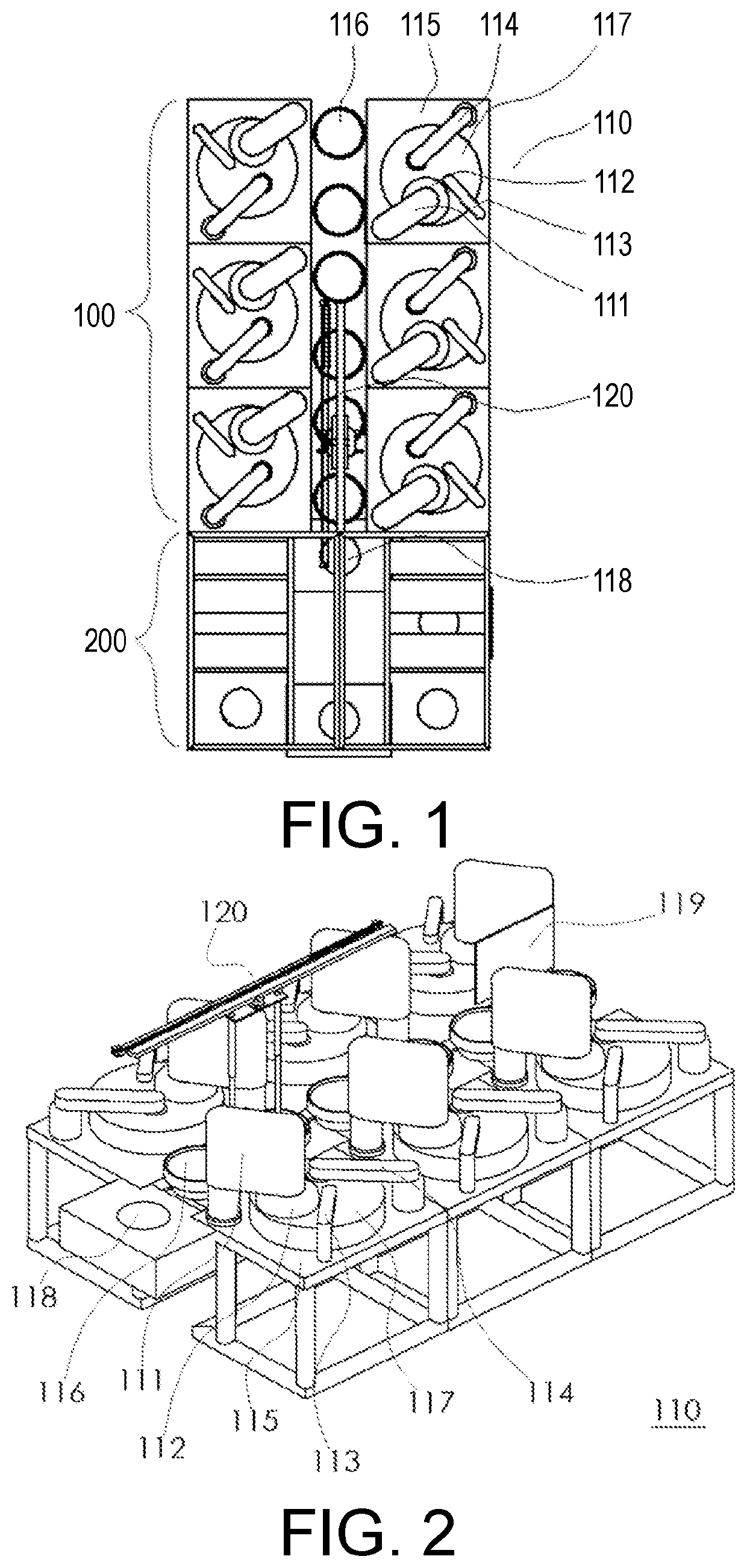
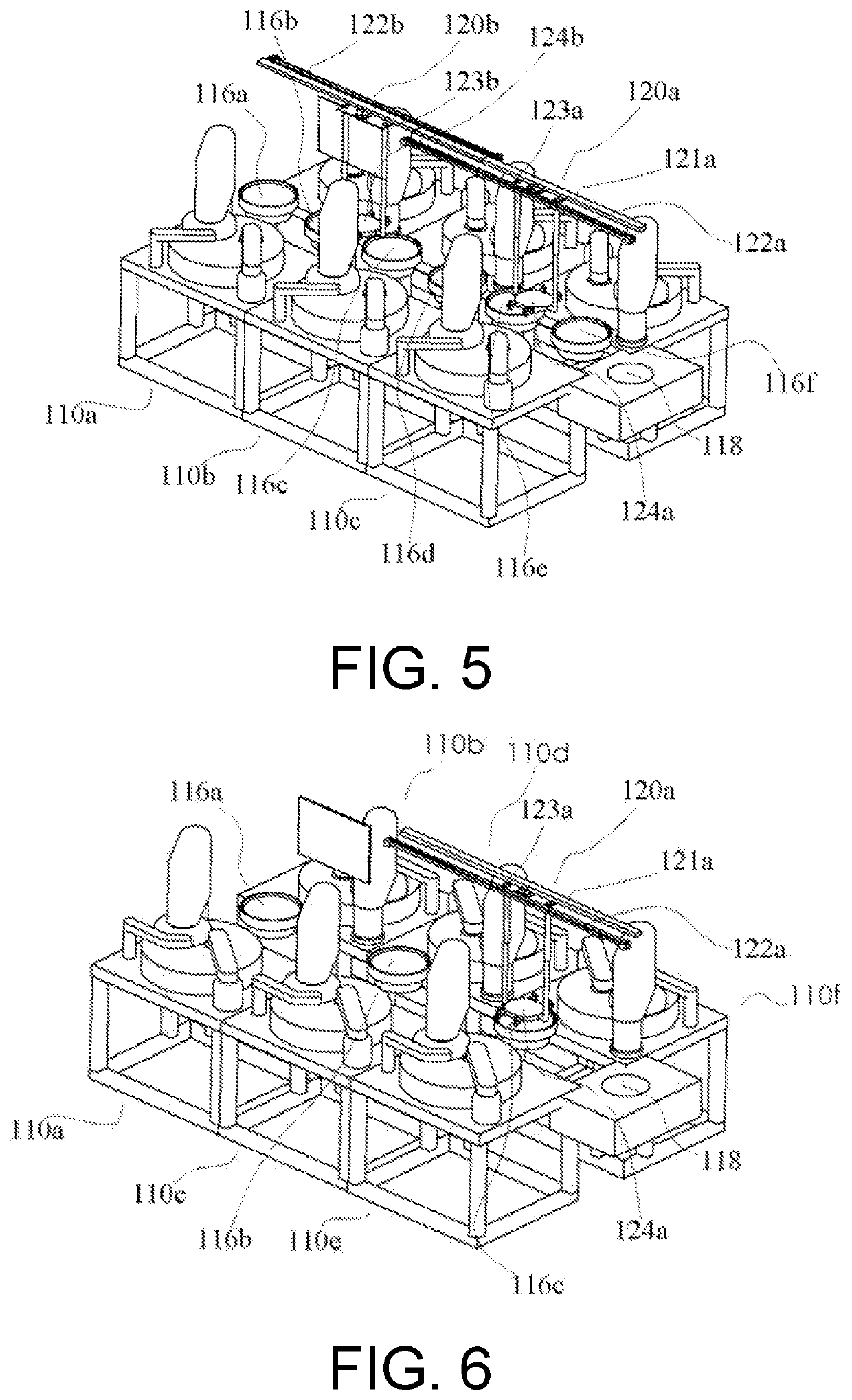
A chemical-mechanical planarization equipment, comprising a polishing module, a cleaning module and a wafer transfer module, wherein the polishing module comprises two rows of polishing unit arrays, each row of polishing unit arrays comprises two or more sets of polishing units, polishing transfer stations corresponding to two rows of polishing unit arrays are longitudinally arranged and located in the row direction of the polishing unit arrays, and a working area of the wafer transfer module is located vertically above the longitudinally arranged polishing transfer stations.

Description

BACKGROUNDTechnical Field[0001]The invention relates to the technical field of semiconductor equipment, in particular to a chemical mechanical planarization equipment, a wafer transfer method, and a wafer planarization unit.Description of Related Art[0002]With the rapid development of semiconductor industry, the critical dimension of integrated circuits continues to be miniaturized, and the high planarization of semiconductor film surface has a significant impact on the high performance, low cost, and high yield of the device.[0003]Chemical Mechanical Planarization (CMP) technology is a combination of chemical and mechanical actions. Its working principle is that the surface material of the workpiece chemically reacts with the oxidizer and catalyst in the polishing liquid to form a soft layer that is relatively easy to remove, and then the soft layer is removed under the mechanical action of the abrasive in the polishing liquid and the polishing pad, and the surface of the workpiece...

Claims


Application Information

Patent Timeline
Patent Type & Authority Applications(United States)
IPC IPC(8): B24B29/02B24B37/30B24B37/34B24B41/06H01L21/304H01L21/306
CPCB24B29/02B24B37/30H01L21/30625B24B41/06H01L21/304B24B37/345H01L21/67219H01L21/68707H01L21/67742H01L21/67173H01L21/67126
Inventor LEE, EDWARDLICANGGU, JINGRAN
Owner HANGZHOU ZHONGGUI ELECTRONICS TECH CO LTD
Why Eureka
Try Eureka