Angle detection optical system, angle detection apparatus, optical signal switch system and information recording and reproduction system

a technology of optical system and angle detection, applied in the direction of recording information storage, instrumentation, disposition/mounting of heads, etc., can solve the problems of deteriorating detection accuracy, limited detection range, and the possibility of providing two apparatuses

Inactive Publication Date: 2006-10-03
OLYMPUS CORP
View PDF13 Cites 31 Cited by
  • Summary
  • Abstract
  • Description
  • Claims
  • Application Information

AI Technical Summary

Problems solved by technology

However, in the technology described in JP-A No. 8-227552, because the relative ratios of outputs of the light receiving surface that is divided into four sections are used, the detection sensitivity at the center position of the light receiving spot and the detection range are restricted by the size of the spot diameter, and these two are in a trade-off relationship with each other.
In addition, because the characteristics of the reflection film directly affect the detection accuracy, the detection accuracy deteriorates unless the reflection film is manufactured with a high level of precision.
Therefore, there are cases when a backup angle detection apparatus is provided in case of a failure in the angle detection apparatus being used.
In such cases, it is only possible to provide two apparatuses in parallel for the above described type of conventional angle detection apparatus.

Method used


Image

  • Angle detection optical system, angle detection apparatus, optical signal switch system and information recording and reproduction system
  • Angle detection optical system, angle detection apparatus, optical signal switch system and information recording and reproduction system
  • Angle detection optical system, angle detection apparatus, optical signal switch system and information recording and reproduction system

Examples


first embodiment

[0030]The angle detection apparatus according to the first embodiment of the present invention will now be described.

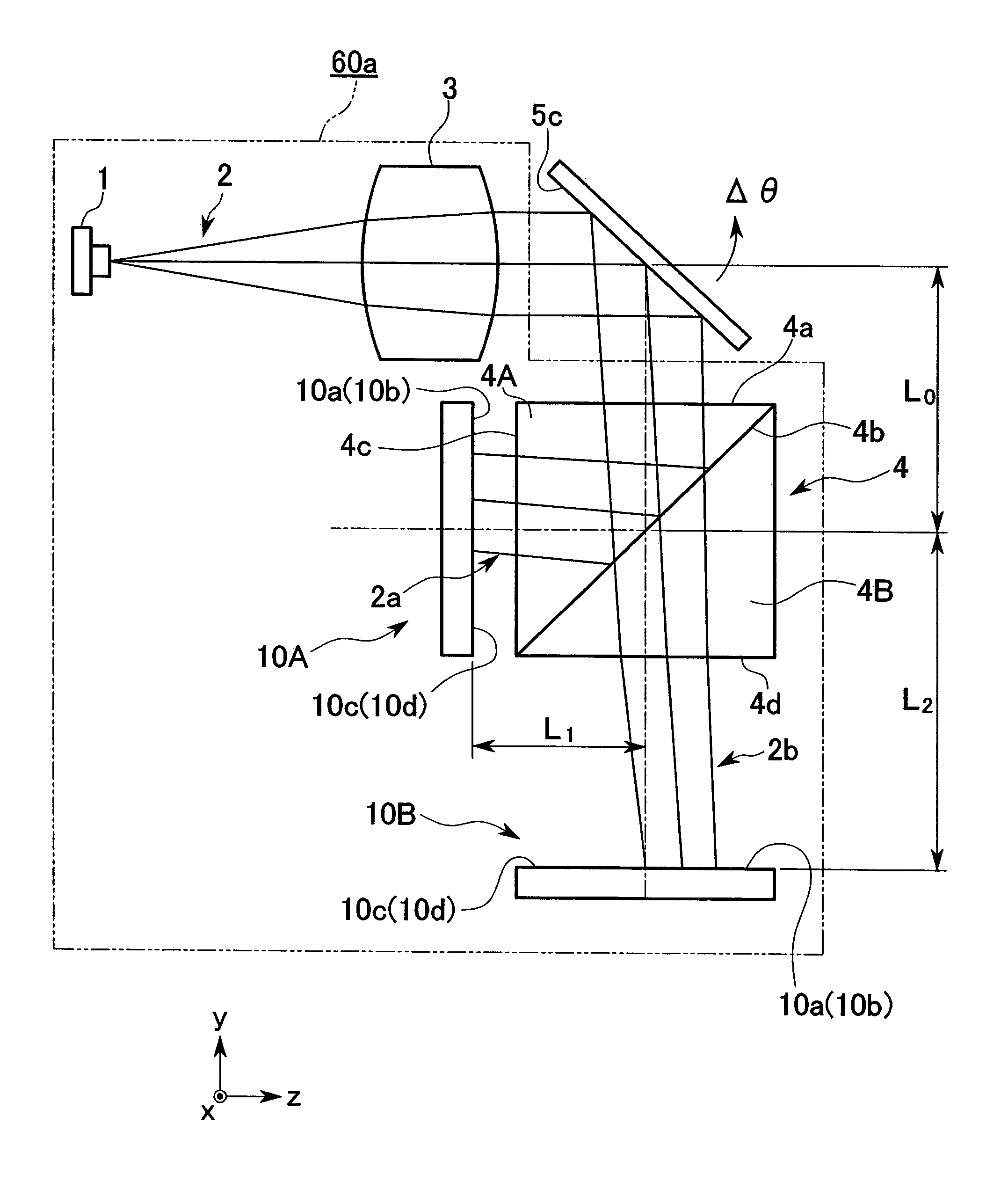
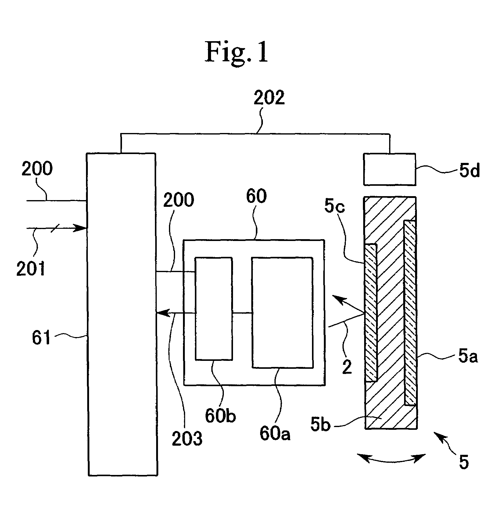
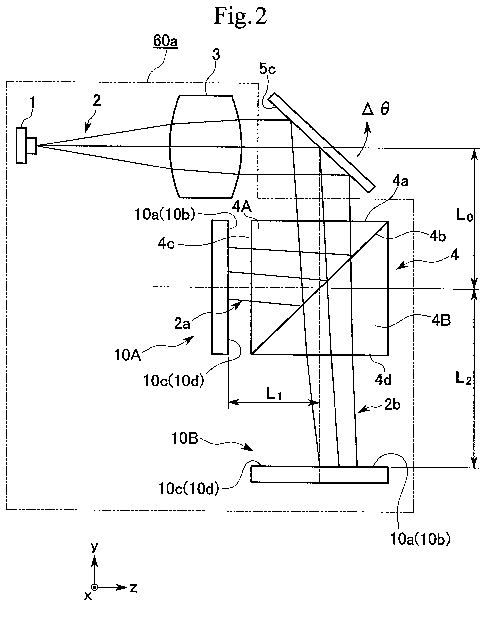
[0031]FIG. 1 is a conceptual view of an angle detection apparatus 60 according to a first embodiment of the present invention. FIG. 2 is a schematic view of an optical path for explaining the schematic structure of a measurement optical system 60a used in the angle detection apparatus 60.

[0032]The angle detection apparatus 60 according to the first embodiment of the present invention is formed by the measurement optical system 60a and a signal processing section 60b, and performs the following operation. Namely, laser light 2 emitted from the measurement optical system 60a is irradiated onto a reflective surface used for detection provided in the object of the angle detection (i.e., the detection object). Reflected light reflected from the reflective surface is then received by the measurement optical system 60a, and signal processing is performed on the received ligh...

second embodiment

[0133]Next, the optical signal switch system according to the second embodiment of the present invention will be described.

[0134]FIG. 10 is a schematic explanatory view for explaining the schematic structure of the optical signal switch system 106 according to the second embodiment of the present invention. FIG. 11 is a control block diagram for explaining the outline of the angle control used in the optical signal switch system 106.

[0135]This system includes an input side cable unit 100 formed by a bundle of optical transmission cables such as optical fiber cables inside which is transmitted laser luminous flux 103 . . . (i.e., optical signals) whose intensity, pulse width, frequency and the like is modulated in accordance with information signals, an output side cable unit 105 formed by a bundle of optical transmission cables such as optical fiber cables inside which is transmitted laser luminous flux 103 . . . , and optical switching devices 108 and 108 that are provided between ...

third embodiment

[0156]Next, the information recording and reproduction system according to the third embodiment of the present invention will be described.

[0157]FIG. 12 is an explanatory plan view for explaining the schematic structure of the information recording and reproduction system 110 according to the third embodiment of the present invention.

[0158]This system is provided with an optical system formed by: a recording disk 112 (i.e., a recording medium) such as, for example, an optical disk or magneto-optical disk that records and reproduces information signals; a semiconductor laser 1 (i.e., a light source) that emits laser beams 115 (i.e., luminous flux) whose intensity and pulse width or the like have been modulated in accordance with information signals; an imaging lens 116 and an imaging lens unit 114 that perform image processing on the laser beams 115; a rotation mirror 5 that is driven to deflect by an actuator (not shown) to perform fine tracking control by deflecting the laser beams...


PUM

PropertyMeasurementUnit
wavelengthaaaaaaaaaa
lengthaaaaaaaaaa

Abstract

A reflective surface for detection is provided in an object being detected. Laser light condensed by a condensing lens is emitted from a laser light source and angle detection is performed by performing angle detection of the reflected light. The reflected light is irradiated onto a beam splitter and the optical path thereof is split by an optical path splitting surface to form luminous flux spots on light receiving surfaces of two four section light receivers. Optical path lengths from the reflective surface for detection to the respective light receiving surfaces are changed enabling the angle detection sensitivity to be altered. In an angle detection apparatus, an optical signal switch system, and an information recording and reproduction system, it is possible to make multiple detections of an inclination angle of a detection object using a compact structure. Consequently, improvements in various performances such as apparatus reliability, inclination angle detection precision, and detection range can be achieved.

Description

BACKGROUND OF THE INVENTION[0001]1. Field of the Invention[0002]Priority is claimed on Japanese Patent Application No. 2002-381816, filed Dec. 27, 2002, the content of which is incorporated herein by reference.[0003]The present invention relates an angle detection optical system to an angle detection apparatus, an optical signal switch system, and an information recording and reproduction system.[0004]2. Description of Related Art[0005]Conventionally, an angle detection apparatus is known that irradiates light from a predetermined position onto a reflective surface used for detection that is provided on a portion of a detection object, and then, by detecting the position of the reflected light, detects the angle from the predetermined position of the detected object.[0006]For example, in Japanese Patent Application Unexamined Publication (JP-A) No. 8-227552 (pages 2–3, FIGS. 1–2) an optical apparatus is disclosed that is provided with a detecting apparatus whose light receiving surf...

Claims


Application Information

Patent Timeline
Patent Type & Authority Patents(United States)
IPC IPC(8): G01B11/26G01C1/00G11B7/09G11B7/13G11B7/135
CPCG01B11/26
Inventor TAKAHASHI, KOICHIARAI, MASAKI
Owner OLYMPUS CORP
Why Eureka
Try Eureka