
Acoustic and thermal energy management system

a technology of acoustic and thermal energy management and a control system, which is applied in the direction of lighting, heating apparatus, and electrical equipment casings/cabinets/drawers, etc., can solve the problems of increasing the noise level of the computer system, increasing the power consumption of the fan, and cpu producing large amounts of heat during operation, so as to reduce eliminate the use of the fan. , the effect of reducing the operation level of the fan

Active Publication Date: 2006-10-03
INT BUSINESS MASCH CORP
View PDF36 Cites 39 Cited by
  • Summary
  • Abstract
  • Description
  • Claims
  • Application Information

AI Technical Summary

Benefits of technology

This approach reduces the acoustic signature and energy usage of electronic devices by minimizing fan operation and extending the time before fan activation, effectively managing thermal energy without continuous fan operation.

Problems solved by technology

Regardless of the construction of the electronic device the CPU produces large amounts of heat during operation.
Several drawbacks are noted with these prior art cooling systems.
First, many of the systems require convection cooling provided by the fan.
Operation of the fan increases power consumption and the noise level of the computer system.

Method used


Image

  • Acoustic and thermal energy management system
  • Acoustic and thermal energy management system
  • Acoustic and thermal energy management system

Examples


Embodiment Construction

[0022]Refer now to the drawings wherein depicted elements are not necessarily shown to scale and wherein like or similar elements are designated by the same reference numeral through the several views.

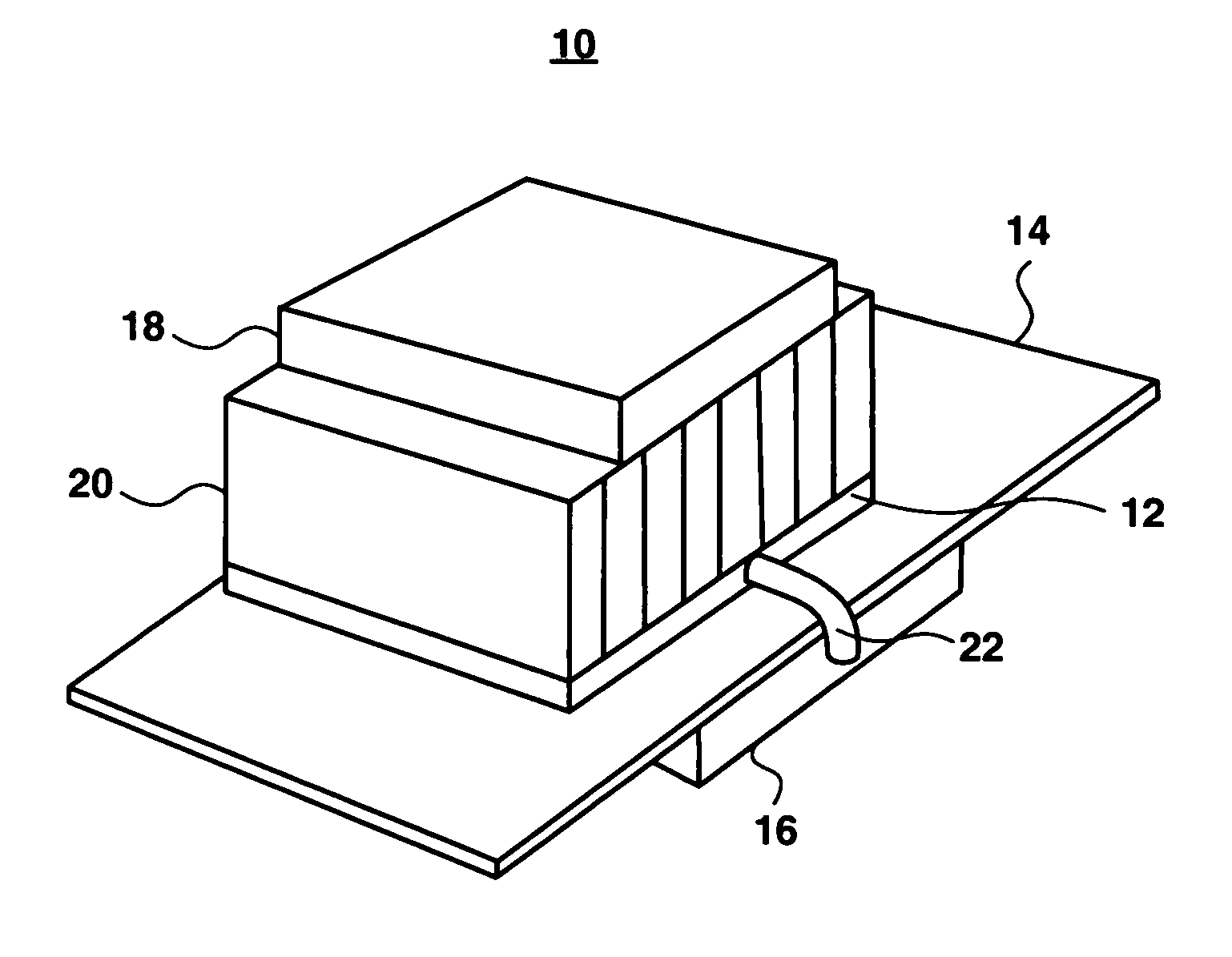
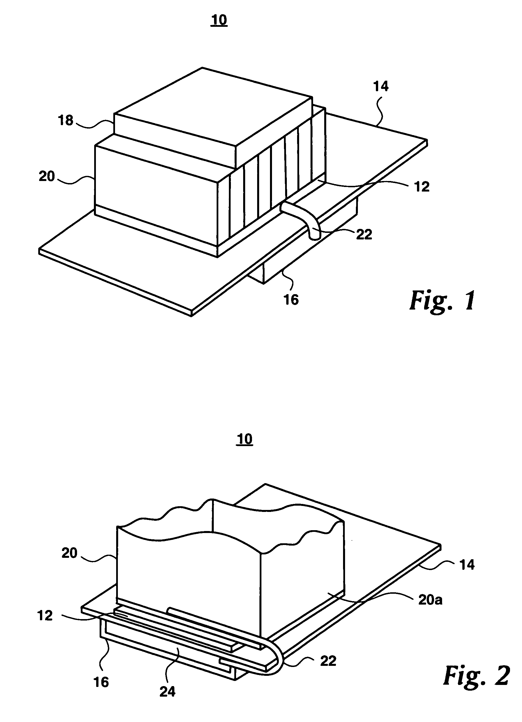
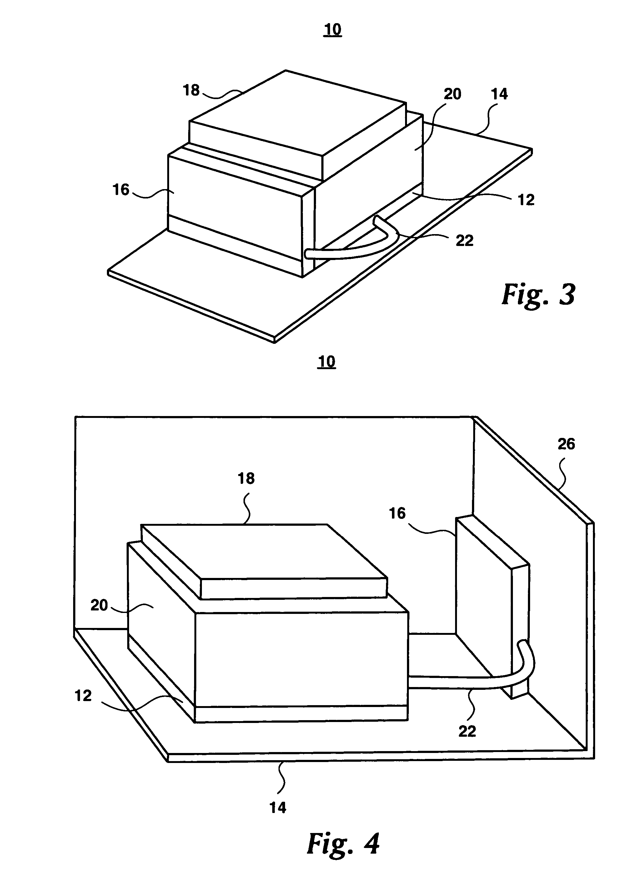
[0023]FIG. 1 is a schematic drawing of the acoustic and thermal energy management system of the present invention generally designated by the numeral 10. System 10 includes a central processing unit (“CPU”) 12, or microprocessor identified as a CPU, a motherboard 14, and a thermal mass 16 connected to CPU 12 via a thermal coupler 22.

[0024]The present invention may also include a fan 18 and a heat sink 20 that is known in the prior art. Typically heat sink 20 will have a heat sink base 20a which is shown in FIG. 2. FIG. 2 indicates that CPU 12 is contacting the heat sink 20 and is located below heat sink base 20a. As shown in FIGS. 1, 3, and 4 heat sink base 20a is included in heat sink 20 and not shown separately so that CPU 12, as the heat generating device, may be more clearly shown....


PUM


Abstract

An acoustic and thermal energy management system and method comprising a microprocessor and a thermal mass positioned at a distance from the microprocessor, the microprocessor and thermal mass being thermally connected to the microprocessor in a manner to transfer thermal energy from the microprocessor to the thermal mass. The acoustic and thermal energy management system transferring heat from the microprocessor to a thermal mass for dissipation reducing the level of heat at the microprocessor, thereby limiting the operation of or the operation level of a fan.

Description

TECHNICAL FIELD[0001]The present invention relates in general to heat dissipation in electronic devices and more particularly to a system for dissipating heat and reducing the acoustics of an electronic device.BACKGROUND INFORMATION[0002]Computer systems typically include an input / output (I / O) port, a central processing unit (CPU), a read only memory (ROM), a random access memory (RAM), and address bus, and a data bus. Computers systems may include numerous other hardware devices and software applications. Regardless of the construction of the electronic device the CPU produces large amounts of heat during operation.[0003]It is necessary to control and maintain the operating temperatures of a computer system below certain levels to ensure performance and reliability of the computer system. Most integrated circuits have specified maximum operating temperatures above which the integrated circuit may fail or slow down as temperatures rise. Therefore the prior art systems typically prov...

Claims


Application Information

Patent Timeline
Patent Type & Authority Patents(United States)
IPC IPC(8): H05K7/20H01L23/427H01L23/467
CPCH01L23/4275H01L23/467H01L2924/0002H01L2924/00
Inventor KAMATH, VINODLOEBACH, BETH FRAYNEMAKLEY, ALBERT VINCENT
Owner INT BUSINESS MASCH CORP
Learn More