Eureka AIR delivers breakthrough ideas for toughest innovation challenges, trusted by R&D personnel around the world.

Dual loop automatic gain control

a gain control and dual loop technology, applied in the field of multi-loop agc circuits, to achieve the effect of sacrificing performan

Inactive Publication Date: 2006-10-03
BROADCOM CORP
View PDF12 Cites 44 Cited by
  • Summary
  • Abstract
  • Description
  • Claims
  • Application Information

AI Technical Summary

Benefits of technology

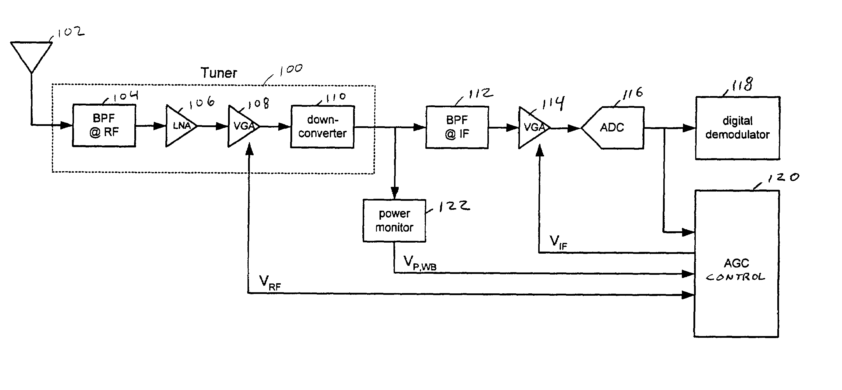
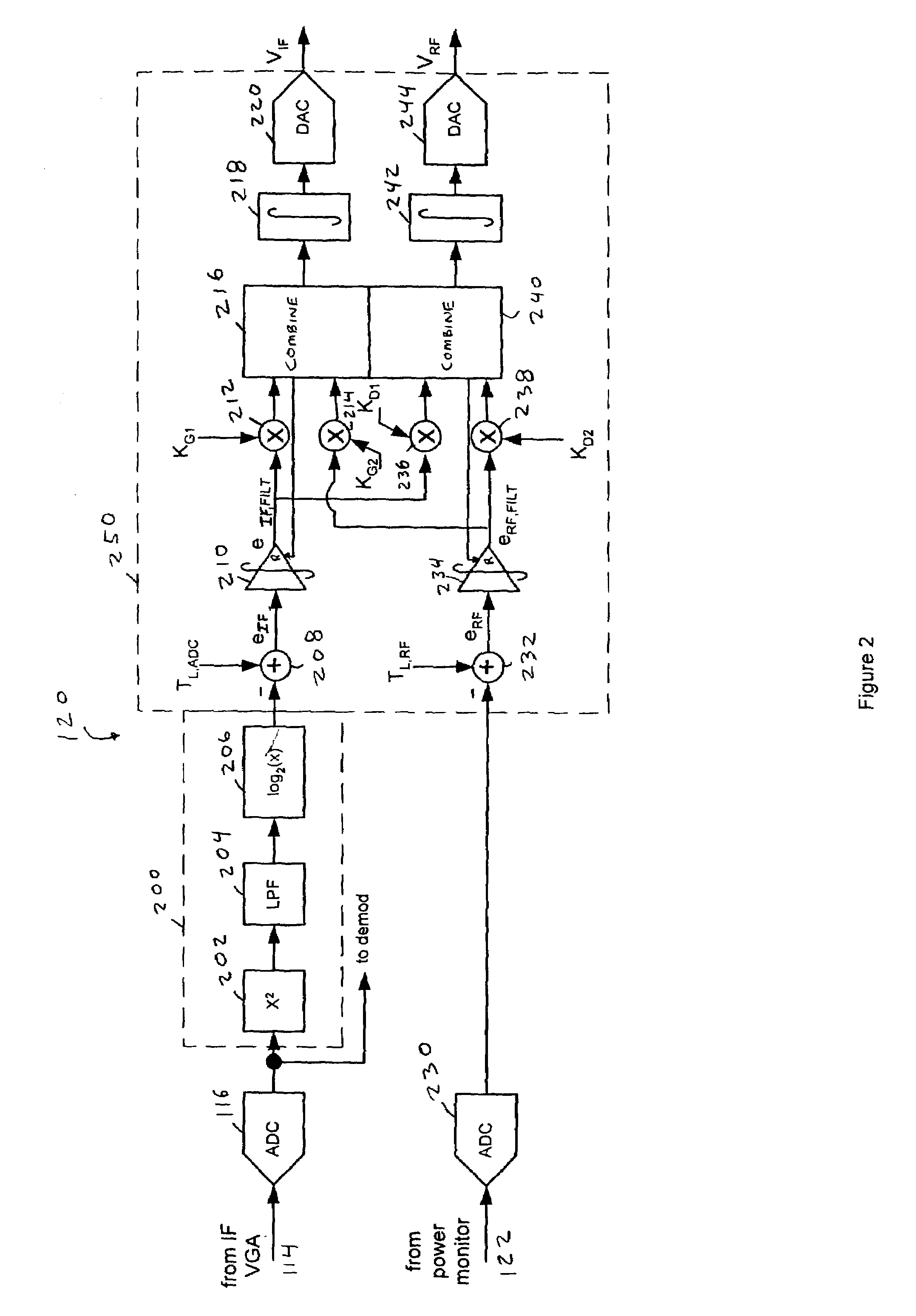
[0004]The present invention is embodied in a novel AGC method and its corresponding circuit which addresses the practical considerations without sacrificing performance related to the fundamental objective of maintaining the desired power level at the demodulator.

Problems solved by technology

Furthermore, because amplifiers can introduce spurious electrical signals (i.e. “noise”) into the signal and because non-linearities in amplifiers and mixers can distort the amplified signal, practical aspects of AGC circuits including device “noise figure” and “linearity” are desirably considered when adjusting the gain of each VGA.

Method used


Image

  • Dual loop automatic gain control
  • Dual loop automatic gain control
  • Dual loop automatic gain control

Examples


Embodiment Construction

[0017]The present invention concerns digital communications receivers that receive a signal through a channel having an attenuation that varies over a large range, is unknown, and often changes dynamically. Specifically, the present invention relates to a method of adjusting the amplification applied to the received signal in response to a desired signal level, other involved signals, and with respect to practical hardware performance constraints. The present invention also concerns the efficient implementation of required operations underlying the AGC algorithm.

[0018]It is desirable for the AGC circuitry to have the characteristics of a linear system so that its operation can be understood and analyzed using the large developed body of linear systems theory. In a particular algorithm, logarithms and exponential functions may be implemented digitally. The present invention employs efficient conversion algorithms suitable for implementation within an integrated circuit or microproces...


PUM


Abstract

An AGC circuit includes both wide-band and narrow-band VGAs. Two power monitors monitor the power level of the two VGAs. Based upon the signals provided by the power monitors, the AGC circuit derives two error terms. The AGC circuit filters and combines the error terms to determine a desired adjustment to the total gain and a desired adjustment to the distribution of the gain between the wide-band VGA and the narrow-band VGA. The AGC circuit also minimizes the noise figure of the narrow-band VGA subject to linearity constraints.

Description

FIELD OF INVENTION[0001]This invention relates to automatic gain control (AGC) circuits and in particular to a multi-loop AGC circuit that divides gain among multiple stages to achieve maximum signal to noise ratio while maintaining distortion below an acceptable limit.BACKGROUND[0002]A typical terrestrial signal receiver includes a wide-band radio frequency (RF) stage in which broadcast signals are amplified. These signals are then converted to an intermediate frequency (IF) by a mixer, filtered and further amplified by an IF amplifier stage to provide a narrow-band signal to a demodulator.[0003]Terrestrial receivers typically include one or more variable gain amplifier (VGA) stages to accommodate the wide range of received signal power that may be encountered in practice. The gains of these amplifiers are adjusted to achieve a desired signal level at the demodulator. For example, one VGA circuit may amplify the broadcast signals at the RF stage and another may amplify the signals ...

Claims


Application Information

Patent Timeline
Patent Type & Authority Patents(United States)
IPC IPC(8): H04B1/06H03G3/30H04B1/10
CPCH03G3/3068H04B1/109
Inventor SCHAFFER, TROY A.HULYALKAR, SAMIR N.SHAH, ANAND M.
Owner BROADCOM CORP
Why Eureka
Eureka Blog
Learn More