Wire-stranded hollow coil body, a medical equipment made therefrom and a method of making the same

a hollow coil and coil body technology, applied in the field of medical equipment, can solve the problems of revealing the structure of the hollow coil body, and achieve the effects of high rotation-following capability, good manipulation response, and high straightness

Inactive Publication Date: 2006-10-10
ASAHI INTECC CO LTD
View PDF19 Cites 123 Cited by
  • Summary
  • Abstract
  • Description
  • Claims
  • Application Information

AI Technical Summary

Benefits of technology

[0016]According to other aspect of the present invention, there is provided a method of making the wire-stranded hollow coil body including a multitude of coil line elements stranded along a predetermined circular line to form a flexible linear tube having an axial hollow portion, the method having steps of clamping one end of a primary forming flexible linear tube by means of a rotationally active chuck, and arranging the other end of the primary forming flexible linear tube to be slidable in its lengthwise direction, and clamping the other end by a fixture chuck to impart a tensile force with the primary forming flexible linear tube; actuating the rotationally active chuck to strand the primary forming flexible linear tube, and concurrently or thereafter heat treating the primary forming flexible linear tube to remove a residual stress upon forming the coil line elements by electrically conducting between the rotationally active chuck and the fixture chuck.
[0019]The wire-stranded hollow coil body is such that characteristics such as a high rotation-following capability and a high straightness are provided to produce a high quality wire-stranded structure in which a group of the coil line elements is stranded to form the flexible wire tube configuration. It is to be noted that the primary forming flexible linear tube may be represented by an ordinary wire rope configuration in which the group of the coil line elements is stranded around an outer surface of an elongated core line.
[0022]The wire-stranded hollow coil body is such that it is stranded under the torsion-resistant load (tensile load in the lengthwise direction), and heat treated to remove the residual stress so as to provide the high rotation-following capability and high straightness. A good manipulation response is obtained at the flexible hollow line wire of the medical equipment upon push-pull manipulating the hand access portion to insert the leading distal end portion into the vascular system or the somatic cavity for an appropriate treatment. The structure enables a manipulator to a good straightness felt before and after inserting into the vascular system or the somatic cavity, and representing a lightweight structure due to the wire-stranded hollow configuration while ensuring a high twisting capability due to a reduced bending rigidity to produce a high quality line wire tube.
[0023]Upon stranding the group of the coil line elements, the flexible linear tube generally generates rolls or swells transmitting in the lengthwise direction due to a contractile stress produced between the neighboring coil line elements tightly arranged and due to a tensile and shearing stress appeared between the coil line elements. In contrast to the above situation, the hollow wire coil configuration according to the invention is stranded under the torsion-resistant load, and heat treated to remove the residual stress. This obviates a chance to occur the detrimental roll or swell phenomenon produced due to the complicated stresses combined, thus providing the wire-stranded hollow configuration with a good straightness. This also achieves a good rotation-following capability in which the leading distal end staunchly follows the rotational manipulation of the hand access portion. The related art wire-stranded hollow coil body disclosed by the first and second references intermittently generates “strand stuck portions”, a part of which is rapidly released with an excessive times of turning operation so as to roll in the stick slip manner. This produces a zigzag curve represented by broken lines in FIG. 31 which indicates that the rotational manipulation of the hand access portion at an angle (θ2) results in twisting the leading distal end by an angle (θ1). On the contrary, the wire-stranded hollow coil body according to the invention is stranded under the torsion-resistant load to eliminate the unfavorable “strand stuck portions” so as to present the high rotation-following capability and high straightness as shown by a linear relationship represented by the solid line in FIG. 31.
[0024]The wire-stranded hollow coil body according to the invention serves as a main wire component of a high quality medical device in which the wire-stranded hollow coil body is equipped with a high rotation-following capability and a high straightness.
[0025]With the former method of making the wire-stranded hollow coil body, it is possible to mass produce the wire-stranded hollow coil body efficiently with a relatively low cost. With the latter method of making the wire-stranded hollow coil body, it is possible to produce the lengthwisely divided sections of the primary forming flexible linear tube to have different strand turns and residual stresses removed in different degrees. This leads to efficiently mass producing the fuctionally gradient type wire-stranded hollow coil body which has a high flexibility at the leading distal end portion, a moderate flexibility at the halfway middle portion and a high rigidity at the rear end portion.

Problems solved by technology

The wire-stranded hollow coil structure disclosed by the fourth to sixth references is unsatisfactory from the point of the indispensable requirement to function as a main linear body for the medical devices because both the references lack the lengthwise linearity and the rotation-following capability while maintaining the uniform torsion-resistant property and flexible property, as is the case with the first and second references.

Method used


Image

  • Wire-stranded hollow coil body, a medical equipment made therefrom and a method of making the same
  • Wire-stranded hollow coil body, a medical equipment made therefrom and a method of making the same
  • Wire-stranded hollow coil body, a medical equipment made therefrom and a method of making the same

Examples


first embodiment

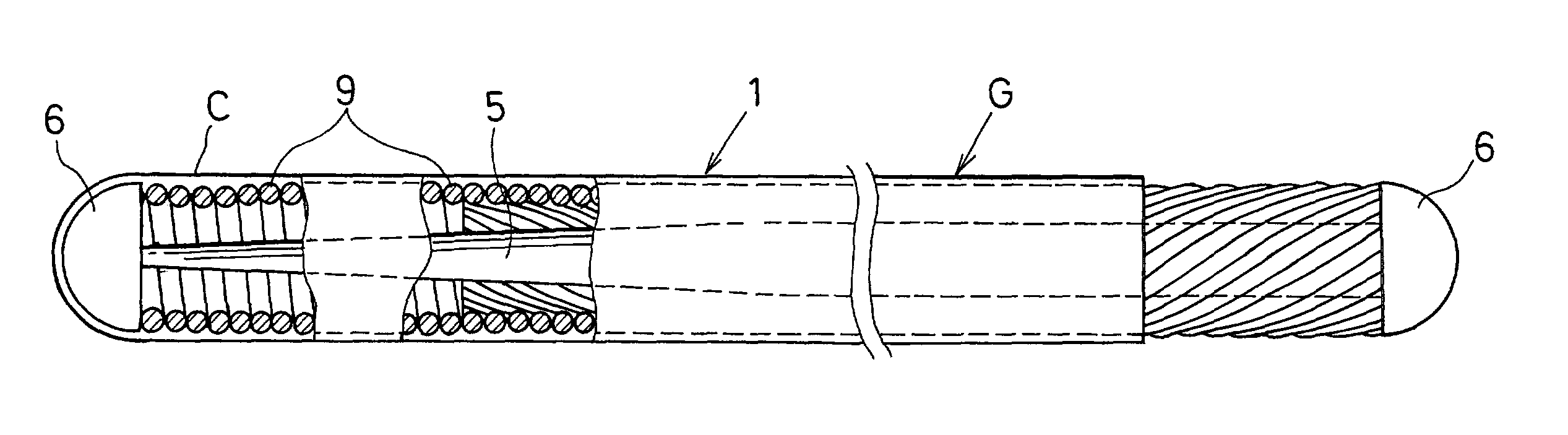
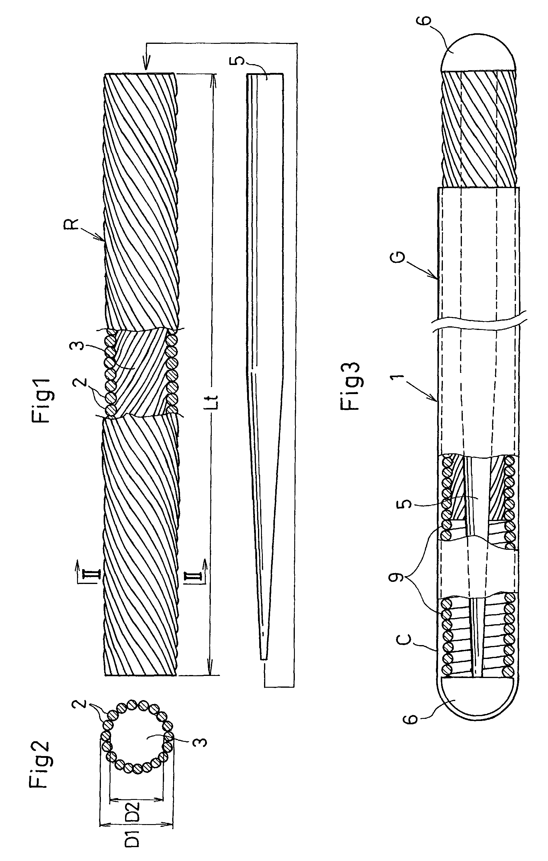
[0058]Referring to FIGS. 1 through 5, with the use of a first method of making a wire-stranded hollow coil body 1, the wire-stranded hollow coil body 1 according to the invention is described. In order to use an enlongated thin flexible wire to a medical guide wire, a multitude of austenitic stainless steel coil line elements 2 are stranded along a predetermined circular line to form a flexible linear metallic tube, a space of which serves as a central axial hollow portion 3. An entire length (Lt) of the flexible linear tube measures approx. 1.000 –1.500 mm.

[0059]The group of the coil line elements 2 is stranded under a strand-turn resistant load (torsion-resistant load) and heat treated to remove a residual stress appeared during the stranding and drawing operation. The wire-stranded hollow coil body 1 thus formed is provided with a high straightness having a straight configuration in free state devoid of the unfavorable roll or swell phenomenon. The wire-stranded hollow coil body ...

second embodiment

[0067]Referring to FIGS. 6 through 17, the invention is described in conjunction with a second and third method of making the wire-stranded hollow coil body 1. The primary approximation R, in which the coil line elements 2 are stranded along the predetermined circular line, is lengthwisely divided into three sections X, Y and Z, each of which has different number of strand turns as shown in FIGS. 6 and 7. When applied to the medical guide wire, the section X has maximum strand turns provided at a hand access portion 8, the section Z has a minimum strand turns provided at the leading distal end 7, and the section Y has a middle number of the strand turns provided at the halfway middle portion. The number of the strand turns progressively decreases from the section X through the section Y to the section Z, a helical pitch of which reversely increases respectively in the same order.

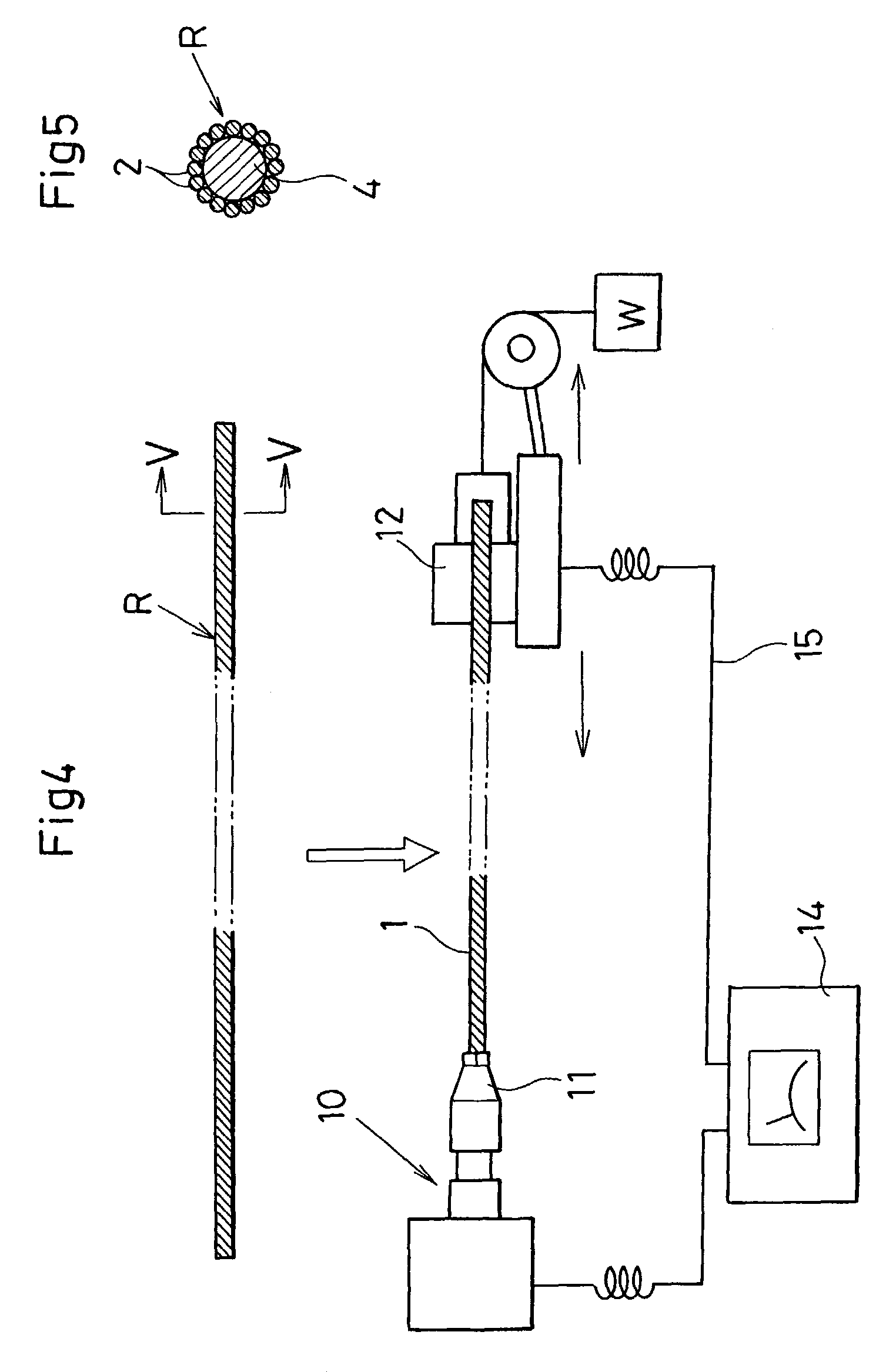
[0068]The wire-stranded hollow coil body 1 is placed between the rotationally active chuck 11 and the fix...

third embodiment

[0070]FIGS. 10 through 12 show the invention in which the individually divided sections X, Y and Z are placed respectively at three heating devices 16A, 16B and 16C each having different heating condition. The primary approximation R is heat treated by energizing the devices 16A, 16B and 16C concurrently at the time of stranding the primary approximation R or after the primary approximation R is stranded, so as to remove the residual stress upon formation by a third method of making the wire-stranded hollow coil body 1. Depending on the heating condition of the heating devices 16A, 16B and 16C, the sections X, Y and Z are heat treated differently to have the residual stresses removed in different degrees. This provides the wire-stranded hollow coil body 1 with the functionally gradient “tensile strength” and “bending rigidity (R2)” each gradually shifting in the lengthwise direction (L) so as to produce a high quality flexible linear tube as shown in FIG. 12.


PUM

PropertyMeasurementUnit
relative friction angleaaaaaaaaaa
flexibleaaaaaaaaaa
tensile forceaaaaaaaaaa

Abstract

A wire-stranded hollow coil body (1) has a multitude of coil line elements (2) stranded along a predetermined circular line to form a flexible wire tube having a central axial hollow portion (3), the flexible wire tube is stranded under a strand-turn resistant load and heat treated to remove a residual stress upon formation so as to provide a high rotation-following capability and a high straightness. Further, a method provides a way to strand the coil line elements (2) under a strand-turn resistant load while heat treating the coil line elements (2).

Description

BACKGROUND OF THE INVENTION[0001]1. Field of the Invention[0002]The invention relates to a wire-stranded hollow coil body used as a main wire component of a medical equipment in the form of flexible line wire such as a catheter, catheter guide wire, endscope treating tool or the like, and more particularly concerns to a medical equipment produced therefrom and a method of making the wire-stranded hollow coil body.[0003]2. Description of Related Art[0004]In a catheter and a catheter guide wire which introduce a leading distal end into a diseased area through a twisted and turned vascular system, a leading distal end of the catheter or the catheter guide wire is inserted into the blood vessel or the somatic cavity by a “push-pull and turn” manipulation at a hand access portion located ouside a subject patient upon treating the diseased area. In an endscope treating tool which is inserted through a somatic cavity to reach the diseased area, a leading end of the endscope treating tool i...

Claims


Application Information

Patent Timeline
Patent Type & Authority Patents(United States)
IPC IPC(8): B21F3/02A61B1/00A61B1/005A61F2/958A61M25/01A61M25/09A61M25/16D07B1/12D07B3/00
CPCA61B1/00071A61B1/005A61B5/417A61B5/6851A61M25/09D07B1/12D07B3/00A61M2025/09108A61M2025/09191D07B5/005D07B2201/2021D07B2207/4063D07B2207/4072D07B5/12D07B2801/60D07B2801/62
Inventor KATO, TOMIHISAMIYATA, KENJI
Owner ASAHI INTECC CO LTD
Why Eureka
Try Eureka