Coaxial cooled laser modules with integrated thermal electric cooler and optical components

a laser module and thermal electric cooler technology, applied in the field of integrated laser assemblies or modules, can solve the problems of unstable optical performance, limited cooling of only the active components (i.e., the ld) and not the passive components, and difficult use of internal cooling with to packages, so as to improve heat dissipation in optical transceivers, facilitate manufacturing, and simplify optical component mounting and alignment techniques

Inactive Publication Date: 2006-10-10
EMCORE INC
View PDF4 Cites 23 Cited by
  • Summary
  • Abstract
  • Description
  • Claims
  • Application Information

AI Technical Summary

Benefits of technology

[0012]It is still another object of the present invention to provide improved heat dissipation in an optical transceiver by using a TEC subassembly inside the housing.
[0013]It is another object of the present invention to provide a cooled optical transceiver for use in an optical transmission system with key optical components packaged in a hermetically sealed enclosure to protect them from exposure to environmental conditions.
[0014]It is another object of the present invention to provide a cooled optical laser module that is easily manufactured by using simplified optical component mounting and alignment techniques.

Problems solved by technology

The use of internal cooling with TO packages has proven difficult due to the limited space within the TO header and the size of the active and passive components found therein.
One previous effort in this regard involved the cooling of a converter module using very small custom thermo-electric coolers (TECs) and was limited to the cooling of only the active components (i.e., the LD) and not the passive components (i.e., lens and isolator).
The cooling of only the active components has been found to result in unstable optical performance where a wide range of operating temperatures are involved.

Method used


Image

  • Coaxial cooled laser modules with integrated thermal electric cooler and optical components
  • Coaxial cooled laser modules with integrated thermal electric cooler and optical components
  • Coaxial cooled laser modules with integrated thermal electric cooler and optical components

Examples


Embodiment Construction

[0028]Details of present invention will now be described, including exemplary aspects and embodiments thereof. Referring to the drawings and the following description, like reference numbers are used to identify like or functionally similar elements, and are intended to illustrate major features of exemplary embodiments in a highly simplified diagrammatic manner. Moreover, the drawings are not intended to depict every feature of actual embodiments or the relative dimensions of the depicted elements, and are not drawn to scale.

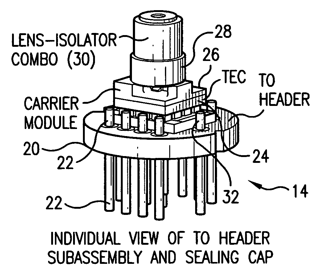
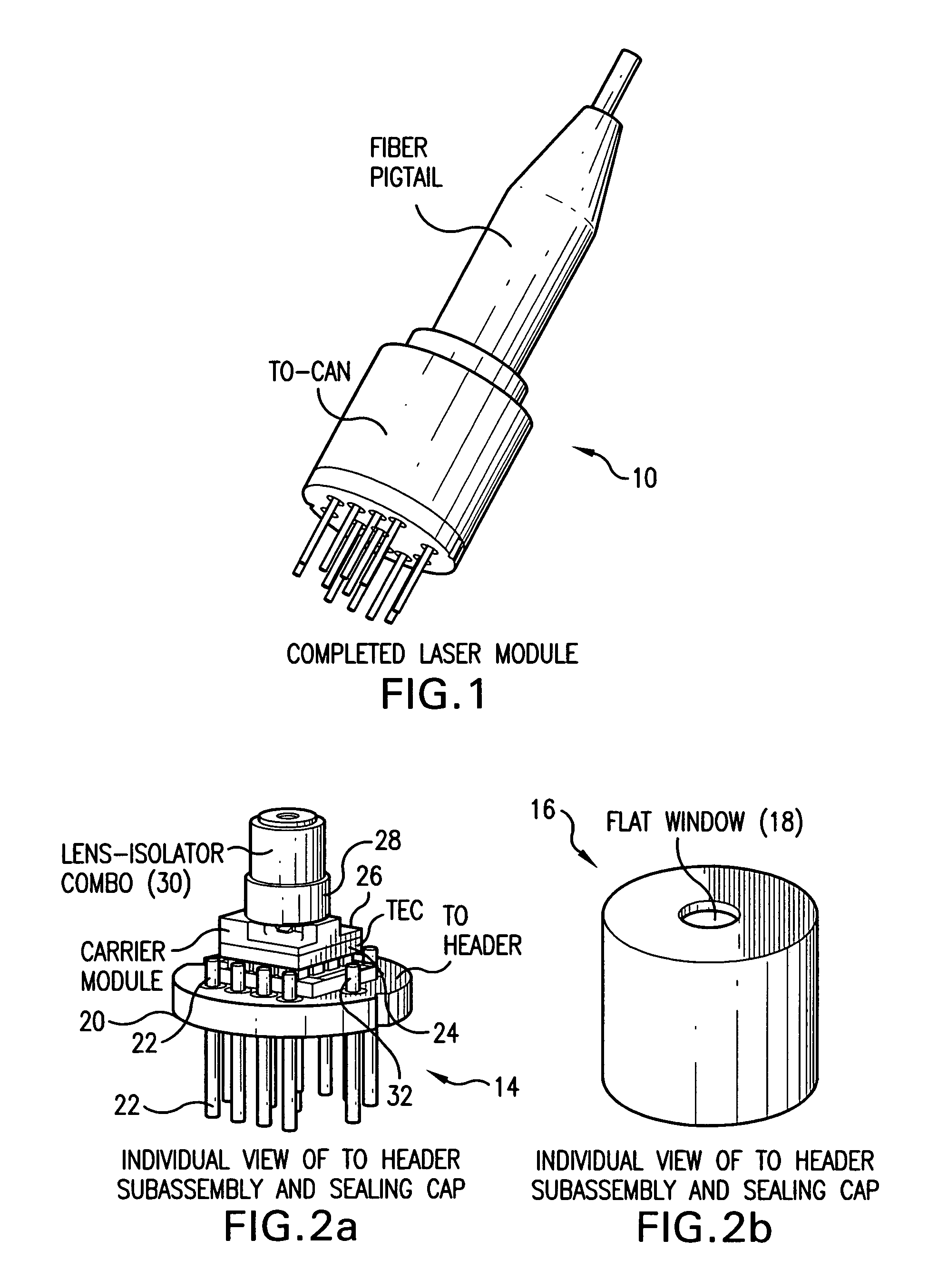
[0029]With this in mind, FIG. 1 shows a coaxially cooled laser module 10 under illustrated embodiments of the invention. The coaxial cooled laser module 10 shown in FIG. 1 consists of a TO-can and a fiber pigtail module 12 which functions to align an axis of light transmission between the TO-can and the optical fiber.

[0030]The embodiments described herein are associated with the TO-can design. Therefore, the discussion provided herein is focused primarily on th...


PUM


Abstract

An opto-electric module adapted to be coupled with an optical fiber on a first side and a plurality of electrical conductors on a second side. The opto-electric module includes a header with a plurality of pins extending through the header a thermo-electric cooler with a hot plate of the thermo-electric cooler disposed against a second, opposing side of the header and a plurality of active and passive optical components adapted to convert between an optical signal format within the optical fiber and an electrical signal format within at least one conductor of the plurality of conductors, said plurality of active and passive optical components all being in thermal contact with a cold plate of the thermo-electric cooler.

Description

FIELD OF THE INVENTION[0001]The invention relates to electro-optical converters, and more particularly to integrated laser assemblies or modules that provide a communications interface between a computer or communications unit having an electrical connector or interface and an optical fiber, such as used in fiber optic communications links.BACKGROUND OF THE INVENTION[0002]This application is related to copending U.S. patent application Ser. No. 11 / 059,790 filed on Feb. 16, 2005 (pending), assigned to the common assignee.[0003]A variety of electro-optic transceivers are known in the art. Such devices typically include an optical laser module that converts an electrical signal into a modulated light beam that is coupled to an optical fiber, and a receiver that receives an optical signal from an optical fiber and converts it into an electrical signal. Traditionally, the optical laser module includes a laser diode (LD) and other optic components and it focus or directs the light from th...

Claims


Application Information

Patent Timeline
Patent Type & Authority Patents(United States)
IPC IPC(8): G02B6/42
CPCG02B6/4246H01S5/02212H01S5/005H01S5/02272H01S5/02284H01S5/024H01S5/02415H01S5/0683H01S5/02251H01S5/0237
Inventor MIAO, RONGSHENGKHA, LEOSWASS, MATTHEW
Owner EMCORE INC
Why Eureka
Try Eureka