Infrared radiation sources, sensors and source combinations, and methods of manufacture

a technology of infrared radiation source and source combination, applied in the field of optical radiation source, can solve the problems of low power efficiency, low efficiency of electrical to useable optical energy, and inability to enjoy wide application, so as to optimize the emitting area and emissivity of the source, improve the effect of waveband emission and maximize power outpu

Inactive Publication Date: 2006-10-10
FLIR SURVEILLANCE
View PDF16 Cites 93 Cited by
  • Summary
  • Abstract
  • Description
  • Claims
  • Application Information

AI Technical Summary

Benefits of technology

[0021]In one aspect, methodology is provided for manufacturing a microbolometer-based SOURCE and integrated sensor. The sensor includes one microbolometer arranged to emit tuned radiation, optics to collect and transmit the radiation to a sample under study for a specific purpose (e.g., to illuminate a gas cell or a solid surface), and another microbolometer arranged to collect at least part of the post sample (i.e., transmitted through the gas or scattered from the surface) radiation. As known in the art, microbolometers function by efficiently collecting infrared radiation within an absorbing microbridge cavity; and the absorbed energy changes the resistance of the bridge electronics, indicating an amount of radiation. The efficient thermal mass of the bridge permits very fast dissipation of radiant energy so that multiple microbolometer can efficiently take high speed IR picture frames (i.e, each microbolometer operating as a pixel in a picture in accord with the invention, the source microbolometer operates in reverse: electric energy drives the microbolometer to radiate heat and to emit radiation in the band of the cavity. The sister microbolometer detector is tuned to the same band and the two microbolometer effectively emit and recover tuned electromagnetic radiation.
[0026]In another aspect, an optical radiation SOURCE is provided which optimizes the following three parameters for improved waveband emissions: operating temperature T(° K), emitting area A, and surface emissivity ε(λ). The SOURCE utilizes structure which emphasizes the emitting surface characteristics (e.g., cavity structure) of the radiator and which optimizes its emitting area and its emissivity to maximize power output in the optimized waveband.
[0027]Another aspect of the invention provides an optical radiation SOURCE with an output that is “spectrally tailored” relative to the emission a perfect blackbody by modifying surface emissivity so as to maximize power output in a desired and controlled spectral wavelength.

Problems solved by technology

Despite the fact that the NDIR gas measurement technique is one of the best methodologies that had ever been devised, it has not enjoyed wide application because of its complexity and high cost of implementation.
Despite the fact that the Nernst Glower gives off an amount of infrared energy with an emissivity close to unity, its power efficiency (i.e., efficiency from electrical to useable optical energy) is notoriously low.
The large amount of unwanted heat is also a major drawback in the use of the Nernst Glower in any NDIR gas measurement systems.
Furthermore, the large heat capacity of the Nernst Glower makes it a necessarily slow device in terms of intensity modulation.
In many cases, it can only be used as a steady state or DC radiation source; and thus a mechanical chopper is needed to generate synchronous modulated signals, further adding to the complexity of NDIR gas measurement systems.
However, such a filament does not have high emission over all wavelengths because there is spatial temperature variation within the filament; it is not an ideal blackbody source.
Prior art hot filaments are thus not particularly good infrared radiation sources for use with NDIR gas sensors.
While the source of the '413 patent advances infrared radiator sources in terms of higher emissivity and wider spectral emissions, it does not offer size or speed advance over the classic tungsten lamp.
Furthermore, its construction is rather fragile and the heater cannot withstand temperatures above −700° C., severely limiting the maximum allowable output.
Finally, its overall power efficiency is rather poor and the low cost and useable life of this radiator has not been satisfactorily proven.
Consequently, the source of the '413 patent has not found wide application in NDIR gas measurement systems.
Nevertheless, other than a slight improvement in power efficiency over the device of '413 patent, there is no fundamental advancement over the prior art.

Method used


Image

  • Infrared radiation sources, sensors and source combinations, and methods of manufacture
  • Infrared radiation sources, sensors and source combinations, and methods of manufacture
  • Infrared radiation sources, sensors and source combinations, and methods of manufacture

Examples


Embodiment Construction

I. Reflector Source with Reflector Housing in Front of Planar Emitter which is Normal to the Emission Axis, in Conjunction with Textured Source

[0057]One form of the invention is a relatively low power reflector infrared (IR) source with an improved texture, smaller (compared to the prior art) filament, and with an integral reflector.

[0058]A common design issue for IR sources is the requirement for significantly more useful signal, particularly in the LWIR, with significantly less required drive power. The present invention effects such changes by including reduced filament size, improved filament texture, and by incorporating a reflector into the source package. This allows, for example, for medical instruments (including anesthesia monitors or critical care systems), industrial safety instruments, and automotive emission monitoring.

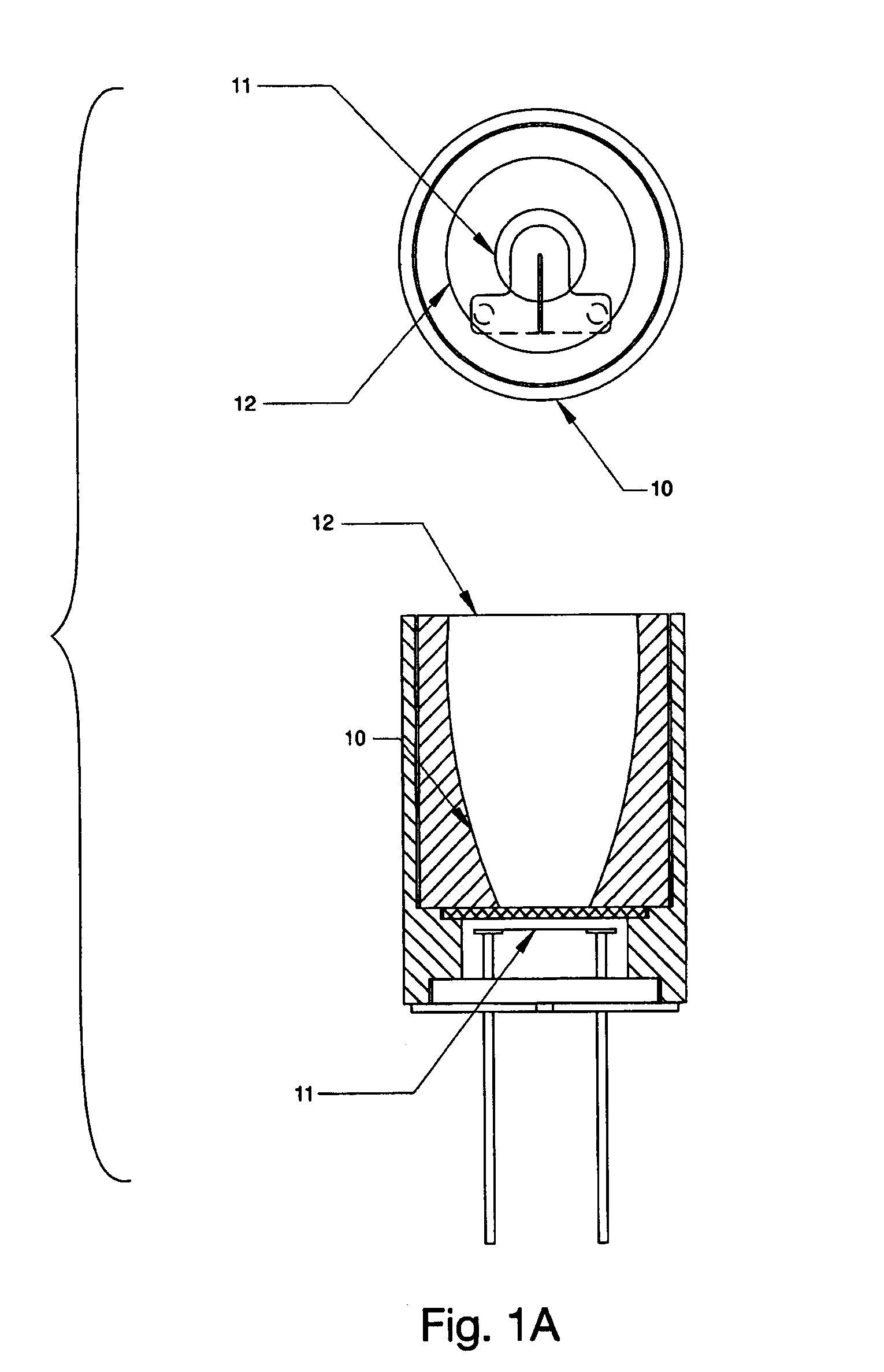
[0059]FIG. 1A shows an IR source 10 of the invention having relatively high usable signal with relatively low drive power. A relatively small filament 1...


PUM


Abstract

A blackbody radiation device (110) includes a planar filament emission element (102) and a planar detector (104) for respectively producing and detecting radiation having width dl / 1 less than about 0.1 to test a sample gas, where 1 is the wavelength of the radiation; a reflector (108); a window (W); an electrical control (118); and a data output element (116).

Description

RELATED APPLICATIONS[0001]This application is a continuation-in-part of commonly owned and U.S. patent application Ser. No. 08 / 905,599, filed on Aug. 4, 1997, now U.S. Pat. No. 5,838,016, granted Nov. 17, 1998, and U.S. Provisional Patent Application Ser. No. 60 / 094,602, filed on Jul. 30, 1998, and PCT Application No. PCT / US98 / 25771, filed Dec. 4, 1998, International Publication No. WO99 / 28729, which are all hereby expressly incorporated by reference. Related PCT Application No. US99 / 07781, filed Apr. 9, 1999, is an appendix to this application.FIELD OF THE INVENTION[0002]This invention relates to optical radiation sources and relates in particular to blackbody radiation sources whose wavelength-dependent surface emissivity is modified in order to radiate with higher power efficiency and / or to radiate within a desired wavelength controlled spectral band. The invention also relates to sensors incorporating sources and to systems and methods embodying same.BACKGROUND OF THE INVENTION[...

Claims


Application Information

Patent Timeline
Patent Type & Authority Patents(United States)
IPC IPC(8): G01J5/02
CPCG01J3/02G01J3/0216G01J3/0286G01J3/108G01J5/0014G01J5/02G01J5/061G01J5/08G01J5/0806G01J5/0809G01J5/0815G01J5/0862G01J5/0893G01J5/0896G01J5/10G01J5/20G01J5/522G01N21/3504G01N21/61G01J5/524G01N2201/06186G01J5/0808G01J5/532G01J5/0802G01J5/53
Inventor JOHNSON, EDWARD A.WOLLAM, JOHN S.DALY, JAMES T.
Owner FLIR SURVEILLANCE
Why Eureka
Try Eureka