Spatial information detecting device using intensity-modulated light and a beat signal

a technology of intensity-modulated light and detecting device, which is applied in the direction of radio frequency controlled devices, instruments, television systems, etc., can solve the problem of a relatively low degree of accuracy in time measurement, and achieve the effect of accurate detecting information and high-speed respons

Inactive Publication Date: 2006-10-10
MATSUSHITA ELECTRIC WORKS LTD
View PDF19 Cites 21 Cited by
  • Summary
  • Abstract
  • Description
  • Claims
  • Application Information

AI Technical Summary

Benefits of technology

[0008]Therefore, a concern of the present invention is to provide a spatial information detecting device using an intensity-modulated light, which has the capability of accurately detecting information about the space such as a distance between an object in the space and the device without using an expensive switching device having high-speed response.

Problems solved by technology

Therefore, as compared with the case of measuring time without frequency conversion, it is possible to perform the time measurement with a relatively low degree of accuracy.

Method used


Image

  • Spatial information detecting device using intensity-modulated light and a beat signal
  • Spatial information detecting device using intensity-modulated light and a beat signal
  • Spatial information detecting device using intensity-modulated light and a beat signal

Examples


first embodiment

(First Embodiment)

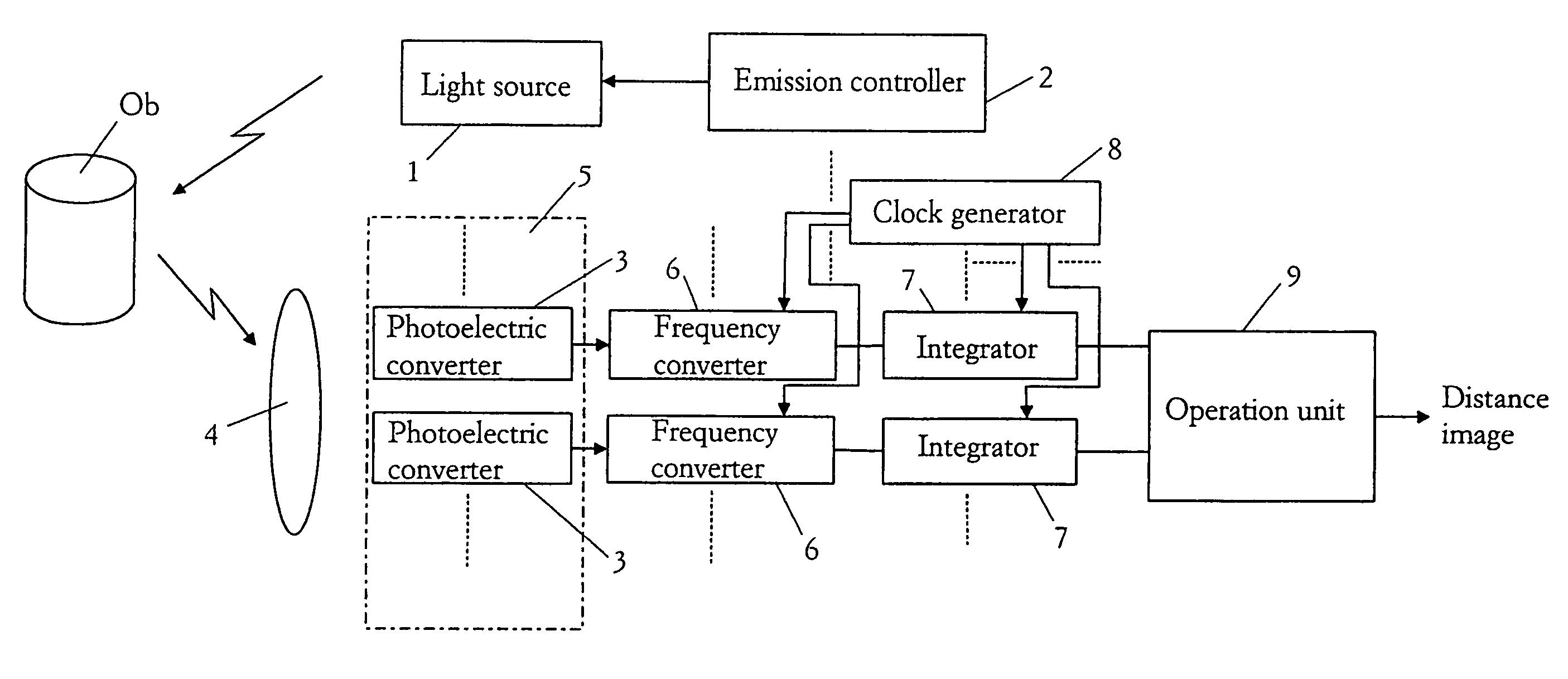
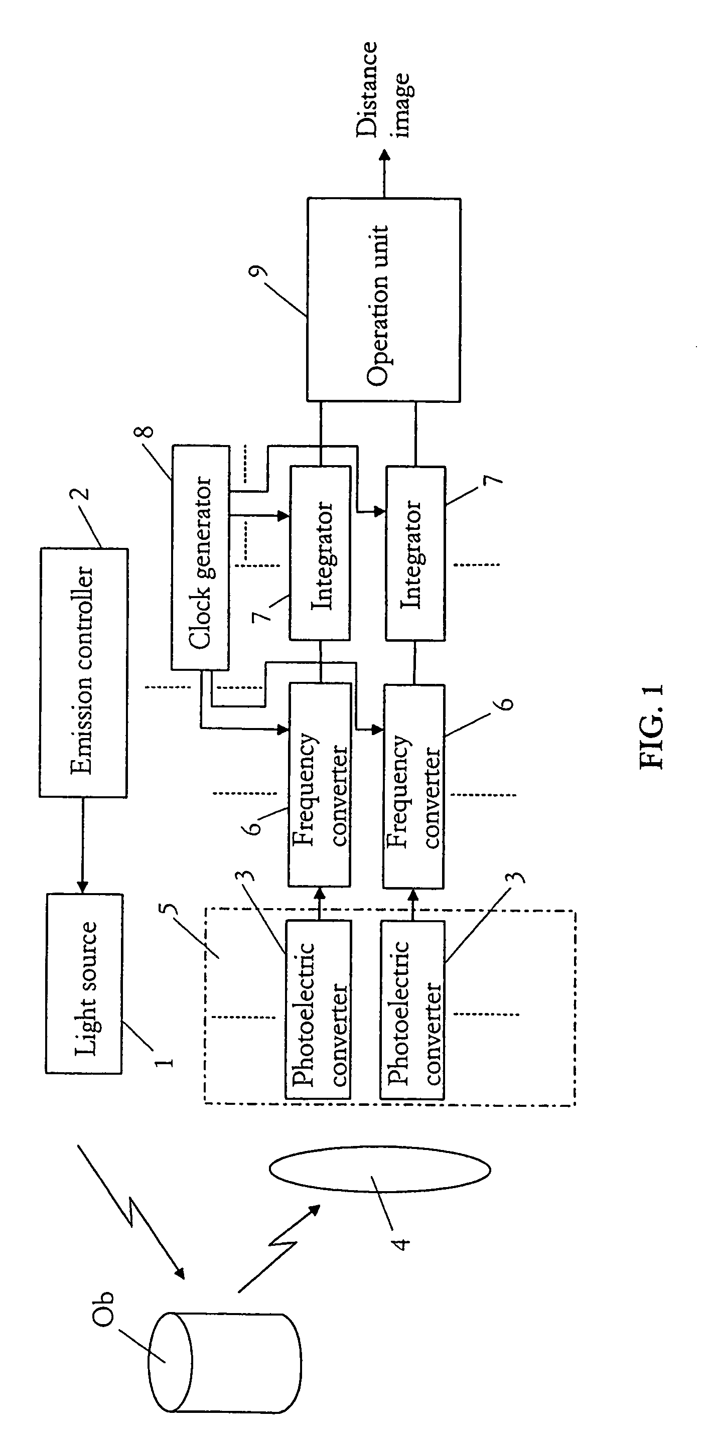
[0061]As shown in FIG. 1, the distance measuring device of this embodiment has a light source 1 for emitting a light into a required space. The light emitted from the light source is intensity-modulated at a predetermined emission frequency by an emission controller 2. As the light source 1, for example, it is possible to use an array of light emitting diodes (LED) or a combination of a semiconductor laser and a divergent lens. As an example, the emission controller 2 intensity-modulates the light emitted from the light source 1 by a sine wave of 20 MHz.

[0062]In addition, the distance measuring device has a plurality of photoelectric converters 3 for receiving a light provided from the space through a lens 4. Each of the photoelectric converters 3 generates an electric output corresponding to an intensity of received light. In other words, the photoelectric converter 3 outputs a receiver signal with a signal level corresponding to the intensity of received light. F...

second embodiment

(Second Embodiment)

[0071]In the first embodiment, the photoelectric converters 3, frequency converters 6, and the integrators 7 are independent of one another. In this embodiment, they are integrally formed as an image sensor 5. That is, as shown in FIG. 3, the image sensor 5 comprises photoelectric converters 3 such as photodiodes, each of which generates, as the receiver signal, amounts of electric charges corresponding to the intensity of received light, memory cells 7a for storing the electric charges generated in the photoelectric converters 3, storage gates 6a, each of which adjusts the amounts of electric charges migrating from the photoelectric converter 3 to the corresponding memory cell 7a, and a transfer circuit 10 that functions as a charge ejector for ejecting the electric charges stored in each of the memory cells 7a to outside

[0072]The storage gate 6a is switched by the local oscillator signal output from a clock generator 8, so that amounts of signal charges correspo...

third embodiment

(Third Embodiment)

[0078]In this embodiment, an interline transfer CCD having a vertical-overflow drain is used as the image sensor 5. As this type of image sensor, it is possible to use one available in the market.

[0079]As shown in FIG. 5, the image sensor 5 is a 2-dimensional image sensor having a matrix arrangement of 3×4 photodiodes 21. The numeral 22 designates a vertical transfer portion composed of a vertical transfer CCD provided adjacent to the photodiodes 21 of each of the columns of the matrix arrangement. The numeral 23 designates a horizontal transfer portion composed of a horizontal transfer CCD provided under the vertical transfer portions. Each of the vertical transfer portions 22 has a pair of gate electrodes (22a, 22b) every photodiode 21. The horizontal transfer portion has a pair of gate electrodes (23a, 23b) every vertical transfer portion 22. The vertical transfer portion 22 is a 4-phase drive, and the horizontal transfer portion 23 is a 2-phase drive. Therefore...


PUM

PropertyMeasurementUnit
emission frequencyaaaaaaaaaa
oscillator frequencyaaaaaaaaaa
frequencyaaaaaaaaaa

Abstract

A spatial information detecting device using an intensity-modulated light is provided. This device comprises a photoelectric converter for receiving a light from a space into which a light intensity-modulated at a predetermined emission frequency is being irradiated, and generating an electrical output corresponding to an intensity of received light; a local oscillator circuit for outputting a local oscillator signal having a local oscillator frequency different from the emission frequency; a sensitivity controller for mixing the local oscillator signal with the electrical output to frequency convert the electrical output into a beat signal having a lower frequency than the emission frequency; an integrator for performing integration of said beat signal at a predetermined timing; and an analyzer for detecting information concerning the space according to an output of the integrator. According to this device, it is possible to accurately detect the spatial information without using a switching element having high-speed response at the light receiving side.

Description

TECHNICAL FILED[0001]The present invention relates to a spatial information detecting device for receiving a light from a space into which an intensity-modulated light is being irradiated, and detecting information concerning the space such as a distance between an object in the space and the detecting device from the received light.Background Art[0002]A technique of detecting various information concerning a space by use of an intensity-modulated light has been known in the past. That is, the intensity-modulated light is irradiated from a light source into the space, and a light reflected from an object in the space is received by a photoelectric converter. According to the relationship between the intensity-modulated light and the received light, the spatial information can be obtained. In the present description, the spatial information includes a distance with object in the space, a change in the amount of received light brought by reflections on the object in the space, and so ...

Claims


Application Information

Patent Timeline
Patent Type & Authority Patents(United States)
IPC IPC(8): G01N21/86H01L27/146G01S7/4914G01S7/493G01S17/36G01S17/894H01L27/148H01L31/02H01L31/103H03D9/00H04N5/30H04N5/335H04N5/369H04N5/372
CPCG01S7/493G01S17/36H01L31/02024H01L31/103H03D9/00G01S7/4914H01L27/14603H01L27/14812G01S17/894G01S17/32G01S17/00
Inventor HASHIMOTO, YUSUKETAKADA, YUJIKURIHARA, FUMIKAZU
Owner MATSUSHITA ELECTRIC WORKS LTD
Why Eureka
Try Eureka