Ghost image correction system and method

a ghost image and correction system technology, applied in the field of ghost image correction system and method, can solve the problems of reducing contrast, reducing signal-to-noise ratio, and reducing the minimum poor system performance and at a maximum product,

Inactive Publication Date: 2006-10-10
LIGHTSHARP
View PDF33 Cites 22 Cited by
  • Summary
  • Abstract
  • Description
  • Claims
  • Application Information

AI Technical Summary

Benefits of technology

[0042]The present invention provides a new and useful method and system for correcting for ghost images in a telecentric optical system. The invention is particularly useful with an optical system in which ghost images are produced by one

Problems solved by technology

These are non-ideal behaviors introduced by the optical elements of an optical system that prevent imaging a point on the object through an optical system to a point on the image.
Diffraction and stray light, however, are inherent parts of the imaging process.
Stray light in optical systems is really unwanted light that is destructive, figuratively and literally, leading to at a minimum poor system performance and at a maximum product, or mission failure.
Stray light obscures faint signals, decreases signal-to-noise ratio, reduces contrast, creates inaccurate radiometric and photometric results, and in high energy laser systems can even destroy optical elements and detectors!
Light incident on painted mechanical mounts in the field of view of the optical system has a high probability of diffusely reflecting (scattering) to the image plane.
Highly polished optical element surfaces are unable to produce perfectly specularly reflected or regular transmitted images.
The process of manufacturing the lenses, such as grinding and polishing, creates micro-cracks at the optical surfaces that create scattered light.
Scattered light is not only caused by subsurface damage created by manufact

Method used


Image

  • Ghost image correction system and method
  • Ghost image correction system and method
  • Ghost image correction system and method

Examples


Embodiment Construction

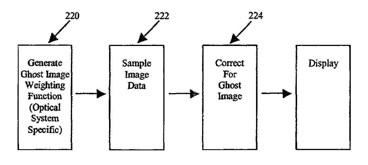
[0062]In the Introduction and Summary, it is explained that ghost images generated from planar optical surfaces in the image space after the major elements of a telecentric optical system, telecentric in image space, are shift invariant. In other words the ghost images produced by these optical elements do not change their shape with different field angles or points. The ghost image's invariance with field position will allow the ghost image to be subtracted or removed from the image of an object recorded on a digital detector such as a CCD or CMOS detector when its optical system is telecentric in image space. This subtraction may be accomplished, for example, with a removal technique using a measured ghost function germane and invariant to that particular optical system. Moreover, the principles of the present invention can also be practiced with a system that is telecentric in object space and with a system which has dual telecentricity.

[0063]A telecentric system which is shift i...


PUM


Abstract

A new and useful method and system for correcting for ghost images in a telecentric optical system is provided. Ghost images generated from planar optical surfaces in the image space after the major elements of a telecentric optical system are shift invariant. In other words the ghost images produced by these optical elements do not change their shape with different field angles or points. The ghost image's invariance with field position will allow the ghost image to be subtracted or removed from the image of an object recorded on a digital detector such as CCD or CMOS detector when its optical system is telecentric in image space. This subtraction may be accomplished, for example, with a removal technique using a measured ghost function germane and invariant to that particular optical system. The combination of the ghost image and scatter functions is linearly shift invariant and therefore, both noise contributions could be removed from the resulting digital image using similar removal techniques.

Description

TECHNICAL FIELD[0001]The present invention provides a method and system for correcting for ghost images in a telecentric optical system.INTRODUCTION[0002]In order to understand the principles of the present invention, it is believed useful to provide the applicant's view regarding the nature of stray light in an optical system, the nature of telecentric optical systems, one software based system and method for correcting for stray light in an optical system, and the nature of ghost images in an optical system, particularly a telecentric optical system.Stray Light[0003]The quality of an image produced by an optical system is a function of diffracting, aberrating, and stray light processes. In fact these processes even occur in the most common optical system, the human eye. All of these processes cause light to spread out from a point source (an infinitesimal, self-luminous point) or a point object (an infinitesimal, illuminated point) when it is imaged through an optical system. Exte...

Claims


Application Information

Patent Timeline
IPC IPC(8): G06K9/40G02B13/22G02B27/00
CPCG02B13/22G02B27/0018
Inventor GARCIA, KEVIN J.
Owner LIGHTSHARP
Why Eureka
Try Eureka