Heat exchange system

a heat exchange fluid and heat exchange technology, applied in the field of energy saving systems, can solve the problems of high energy cost, and achieve the effect of facilitating the transport of heat exchange fluid

Inactive Publication Date: 2006-10-24
LINNEY JOHNATHAN W
View PDF7 Cites 32 Cited by
  • Summary
  • Abstract
  • Description
  • Claims
  • Application Information

AI Technical Summary

Benefits of technology

[0007]A vessel to accommodate thermal expansion of the pressurized heat exchange fluid in communication with the first heat exchanger, the second heat exchanger, the third heat exchanger or combinations thereof. The vessel receives pressurized heat exchange fluid and at least one pump facilitates the transporting of heat exchange fluid through the first heat exchanger, the second heat exchanger, the third heat exchanger, the vessel and combinations of them.

Problems solved by technology

This need has been driven by the high cost of energy.

Method used


Image

  • Heat exchange system
  • Heat exchange system
  • Heat exchange system

Examples


Embodiment Construction

[0014]Before explaining the present invention in detail, it is to be understood that the invention is not limited to the particular embodiments herein and it can be practiced or carried out in various ways.

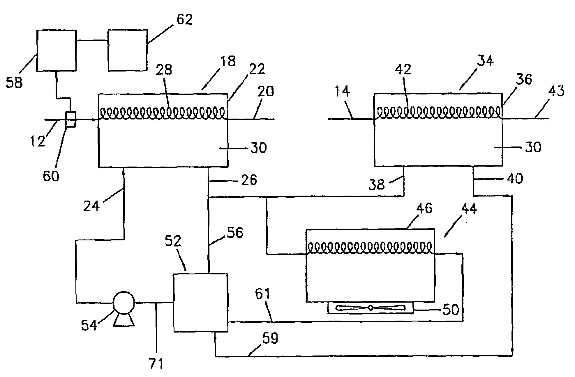
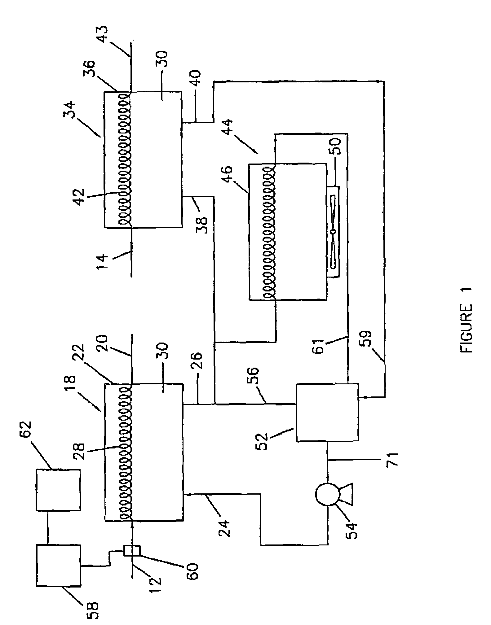
[0015]The invention relates to a system for heating hydrocarbon flows using heated compressed air, such as from a compressor exhaust, rotor exhaust, or from compressed air available at a power plant.

[0016]As the need for higher efficient power plants increases, there is a need for improving the performance of gas fuel heating to improve overall plant efficiency. By essentially preheating the fuel, such as fuel gas to a range of 365 degrees F., gas turbine efficiency is improved by reducing the amount of fuel needed to achieve the desired firing temperatures. Fuel heating is viable and the present invention is directed to a method for fuel heating to improve the plant efficiencies and recycle the heat exchange fluid through a series of heat exchangers.

[0017]FIG. 1 shows an overview...


PUM


Abstract

The invention is a system for heating hydrocarbon flows with three heat exchangers, wherein the first heat exchanger transfers heat from compressed heated air to a pressurized heat exchange fluid; wherein the second heat exchanger transfers heat from the pressurized heat exchange fluid to a hydrocarbon flow and increases the hydrocarbon flow temperature between 50% and 900%; wherein the third heat exchanger receives the pressurized heat exchange fluid from the first heat exchanger and cools the fluid using at least one fan located in the third heat exchanger; and the system also has a vessel to accommodate thermal expansion of the pressurized heat exchange fluid and at least one pump for transporting fluid through the system.

Description

FIELD OF THE INVENTION[0001]This invention relates to an energy saving system for using compressed heated air to heat a heat exchange fluid, which in turn is used to heat a hydrocarbon stream without the need for the use of additional energy.BACKGROUND OF THE INVENTION[0002]A need has existed for a lower cost, fuel efficient system to heat a hydrocarbon stream for subsequent combustion using existing heated air streams already present at a chemical plant, power plant or refinery. This need has been driven by the high cost of energy. A need has existed, which lowers the cost of heating a hydrocarbon stream for combustion.[0003]The present invention is a closed loop system utilizing a plurality of heat exchangers and an existing heated air stream to raise the temperature of fuel or a hydrocarbon stream by at least 50% up to 900%.SUMMARY OF THE INVENTION[0004]The invention is a system for heating hydrocarbon flows, comprising a first heat exchanger having a housing, a compressed heated...

Claims


Application Information

Patent Timeline
Patent Type & Authority Patents(United States)
IPC IPC(8): F01K7/32F01K13/00F01K25/06F01K25/08F03G7/00
CPCF02C7/224F28D21/0014
Inventor LINNEY, JONATHAN W.BIBB, MICHAEL B.BAUER, TIMOTHY RAY
Owner LINNEY JOHNATHAN W
Why Eureka
Try Eureka