Method and apparatus for intraluminal fixation of intravascular devices

a technology for intravascular devices and fixation methods, applied in the field of medical techniques, can solve the problems of limited functional possibilities, complicated and insufficiently reliable design, and inoperable apparatus design suggested by tahery

Inactive Publication Date: 2006-10-24
E S VASCULAR
View PDF2 Cites 9 Cited by
  • Summary
  • Abstract
  • Description
  • Claims
  • Application Information

AI Technical Summary

Benefits of technology

[0067]Besides, the stapler may be additionally provided with an optical system for observing the positioning of the working head of this stapler relative to the surface of a corresponding intravascular device, as well as the location on this surface of fastener means for securing the intravascular device to the wall of a blood vessel. The optical system includes at least an optical lens connected via optical fibers with an optical monitor located at the surgeon's working place. In his case at least one of the optical fibers serves for lighting up the spots of location of fastener means for securing the intravascular device to the blood vessel wall.

Problems solved by technology

The apparatus design suggested by Tahery is, in our opinion, inoperative as the radial force generated by a balloon is inadequate to insert a securing member shaped as a nail into the wall of the aorta or artery.
All the described inventions by Howard Tanner have, in our opinion, a complicated and not adequately reliable design and limited functional possibilities.
So, in particular, the apparatus for setting the securing elements cannot be brought in operative position inside iliac arteries having a small lateral diameter.
Because of limited space it is impossible to bend the end of the apparatus working head for setting the securing elements in the stent-graft wall.
The efficiency of this apparatus for drilling holes in the walls of the stent-graft, aorta and iliac arteries is doubted, especially if these walls are calcified and covered by calcium plaques.
As far as the suggested securing elements are concerned, we believe that their fixation in the inner walls of the aorta and iliac arteries is not reliable enough.
Therefore, under the action of blood flow and peristaltic oscillations of artery walls, the stent-graft may be displaced from its proper position, which may have grave consequences for the patient and may result in his death due to the aorta rapture.
This device is essentially complicated in design, and the main drawback of it is that it is impossible to bend the ends of staples when they are extended from the device body outside, through the prosthesis and wall of the blood vessel.
Therefore it is necessary to provide the device with anvils located outside the operated blood vessel, which makes the device itself and the whole surgical procedure for setting a stent-graft considerably more complicated and expensive.
So it is a difficult procedure to set the staples, as it is necessary to achieve very precise positioning of the device relative to the prosthesis wall.
It is impossible to set simultaneously several staples with this device design.
Besides, an essential part of staples project inside the prosthesis, which may result in accelerated thrombogenesis in this inner lumen of the prosthesis.

Method used


Image

  • Method and apparatus for intraluminal fixation of intravascular devices
  • Method and apparatus for intraluminal fixation of intravascular devices
  • Method and apparatus for intraluminal fixation of intravascular devices

Examples


Embodiment Construction

[0082]The preferred embodiments of the present invention are described below. The inventors of the present subject matter contemplate that the embodiments described herein are capable of use in the repair of other vessels and in other procedures. Thus, it is intended that the present invention cover the modifications and variations of the invention, provided they come within the scope of the appended claims and their equivalents.

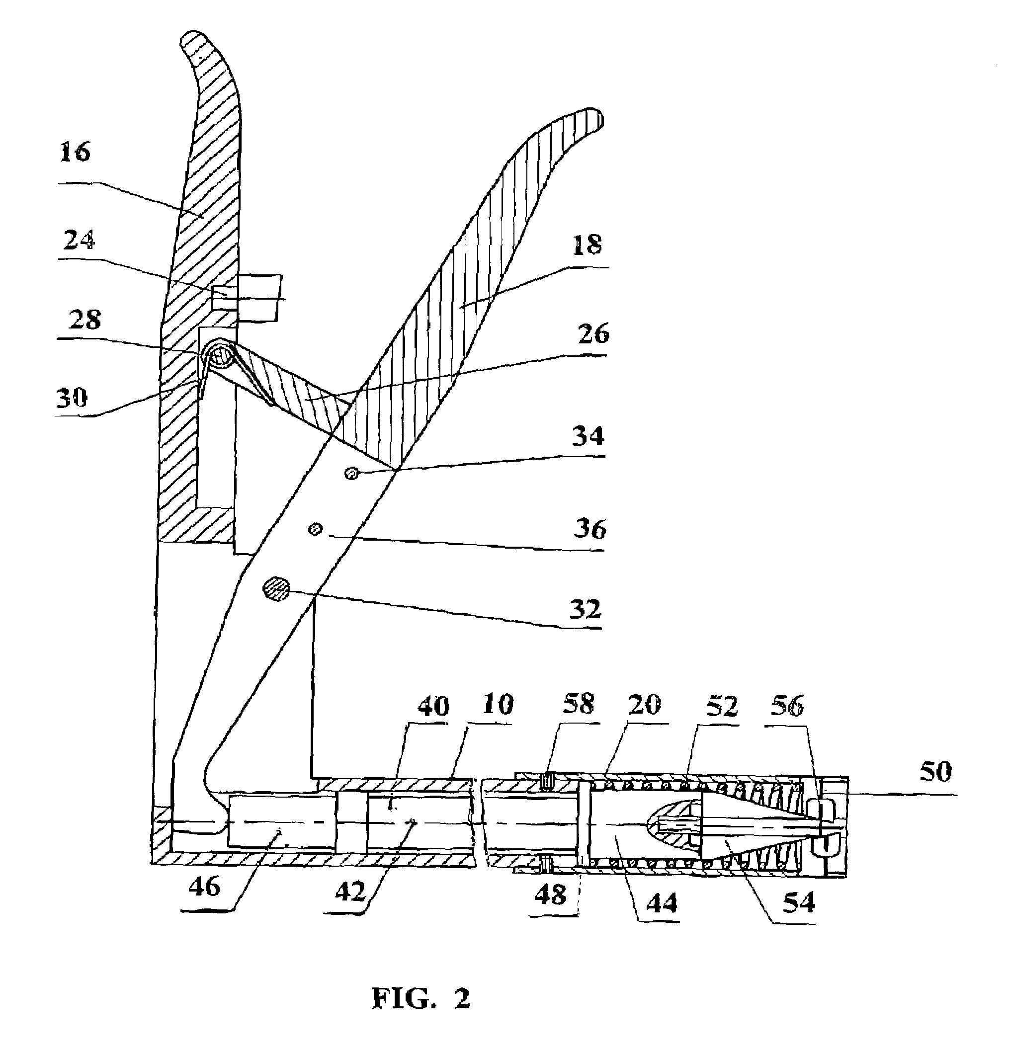
[0083]The most preferred embodiments of a stapler, according to the present invention, are shown in drawing FIGS. 1 and 2–28.

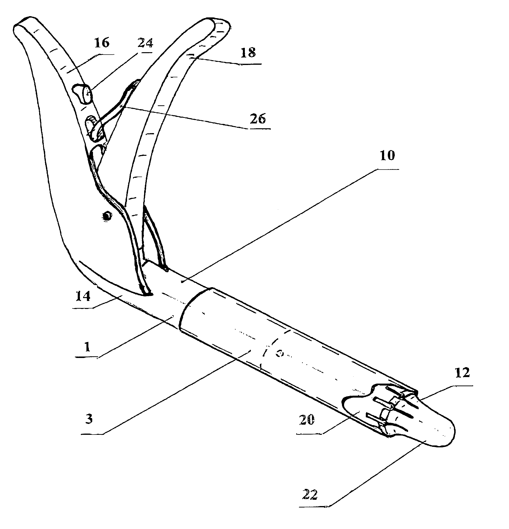
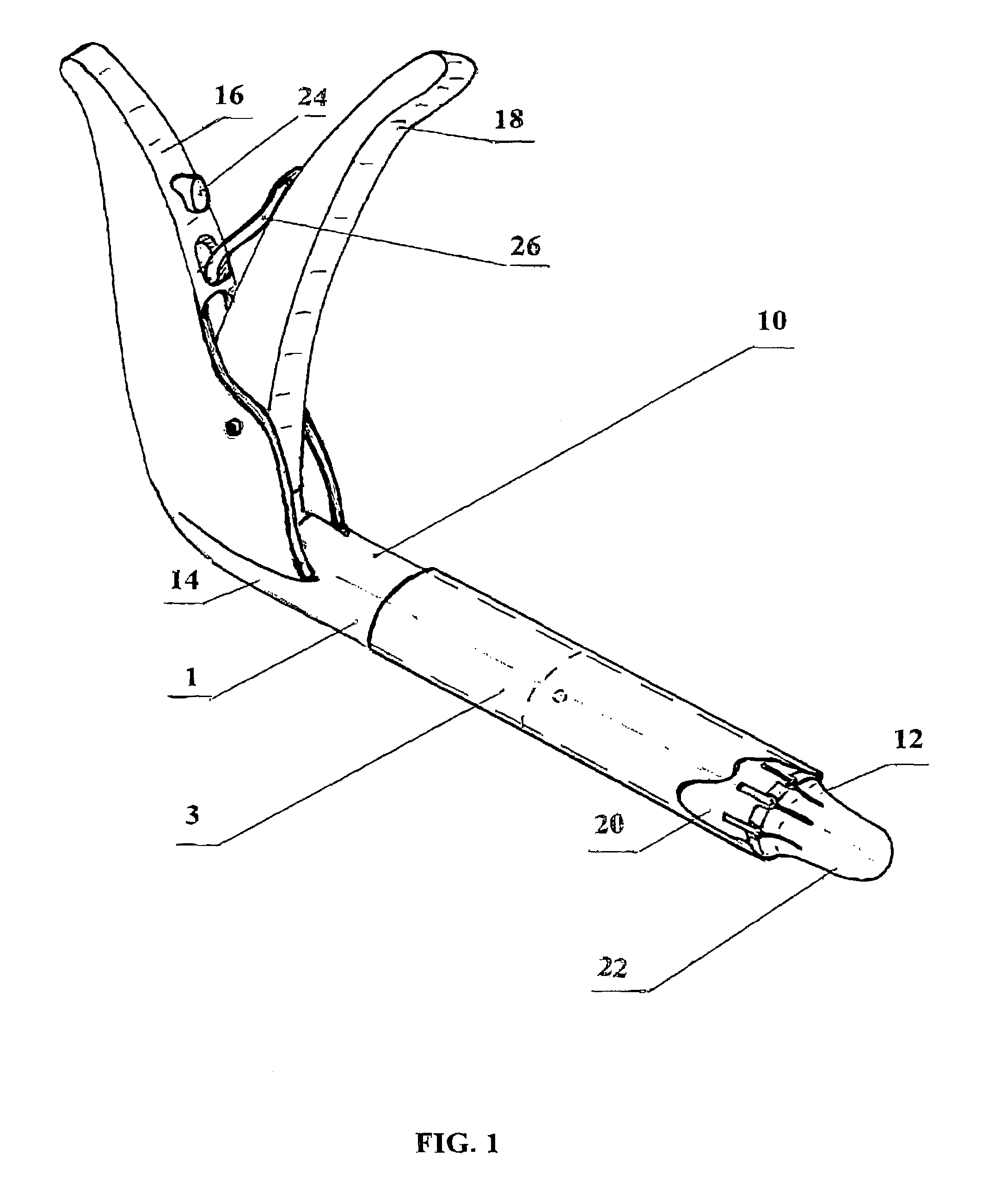
[0084]The present invention (FIG. 1) includes a stapler 1 for intraluminal fixation of intravascular devices, substantially grafts 3, located inside blood vessels, using minimally invasive surgery techniques.

[0085]Stapler 1 comprises a hollow body 10, substantially cylindrical in shape (FIG. 1), having a proximal end 12 and a distal end 14 with a holding handle 16 extending therefrom at a certain angle, not exceeding 90 degrees, and a ...


PUM


Abstract

The present invention rerlates to medical techniques, in particular, to methods and apparatus applied in minimally invasive vascular surgery to eliminate occlusion of blood vessel, using grafts and to prevent rupture of abdominal aorta using grafts or stent-grafts. More particularly, the present invention relates to methods and apparatus for locating and securing intravascular devices, substantially grafts, through a duct specially created by the surgeon to approach the blood vessel lumen. There is suggested a new and improved method for fixating an intravascular device to a blood vessel wall in combination with a new and improved stapler design based on this method. The stapler comprises a hollow body at the proximal end whereof there are mounted a guiding head and a die, and at the distal end, at a certain angle to the latter, a holding handle and a control lever, pivotally connected to this handle, and this control lever is operatively connected, via a movable pressure member, to a tip located inside the body, head and die. In the die there are disposed fastener means. The movement of control lever is converted into radial forces necessary for punching the wall of an intravascular device and surrounding blood vessel wall, location and fixation of fastener means, with simaltaneous bending of their ends. For maximum sinking of heads of fastening elements in the wall of an intravascular device, additional pushing members are movably mounted in radial slots of the die. The intravascular device, substantially graft, is fixated to a blood vessel wall, substantially aorta, via a set of at lest two staplers, and in each of the staplers there are disposed simultaneously several fastener means.

Description

BACKGROUND OF THE INVENTION[0001]1. Field of the Invention[0002]The present invention relates to medical techniques, in particular, to apparatus and methods used in minimally invasive vascular surgery using grafts for eliminating occlusion of blood vessels or stent-grafts for preventing rupture of abdominal aorta, as well as to methods for their location and fixation. More particularly, the present invention relates to methods and apparatus for securing intravascular devices, such as grafts or stent-grafts, to the walls of blood vessels in direction from inside these vessels to their outer surface.[0003]2. Description of Related Art[0004]Occlusion of great blood vessel resulting from formation of calcic or adipose deposits on their inner walls, or from thrombogenesis causes deterioration of blood supply to most important organs, such as the heart and brain, and to such dangerous situations for the patient, as infarction or insult.[0005]To prevent occlusion of great blood vessels, in...

Claims


Application Information

Patent Timeline
Patent Type & Authority Patents(United States)
IPC IPC(8): A61B17/10A61B17/068A61B17/12A61F2/06
CPCA61B17/068A61B2017/1205A61F2/07A61F2002/065
Inventor SHIFRIN, EDWARDUMANSKY, MARKSHVARTSMAN, MORDEHYNICKELSHPUR, GENNADYMOORE, WESLEY
Owner E S VASCULAR
Why Eureka
Try Eureka