Device and method for production of carbon nanotubes, fullerene and their derivatives

a technology of carbon nanotubes and fullerene, which is applied in the field of devices and methods for producing carbon nanotubes, fullerene and their derivatives, can solve the problems of reducing the time of permanence of carbon clusters in high temperature plasma, affecting the research of other new applications, and affecting the development of new applications. , to achieve the effect of eliminating any trace of atmospheric gases

Inactive Publication Date: 2006-10-24
CARBONIUM
View PDF6 Cites 12 Cited by
  • Summary
  • Abstract
  • Description
  • Claims
  • Application Information

AI Technical Summary

Benefits of technology

[0040]Advantageously, it is possible to utilize; i) graphite rods with ends appropriately machined to stack up the rods in a way that the previous rod sustains and pushes the next one inside the chamber.
[0042]It is advantageous to utilize a vacuum chamber having one port for the inlet of an inert gas through a pressure and flow intercepting and regulation system, and another port, on the opposite side, for inert gas evacuation. From the same evacuation port it is also possible to pump down the vacuum in the chamber and, during the process, to suck away the inert gas that carries the reaction products.
[0043]Consequently, by these two ports it is advantageously possible to control with precision both inert gas flow and pressure inside the chamber.
[0044]According to the present invention, after that the end of the first rod has been inserted in the chamber, the vacuum is produced to eliminate any trace of atmospheric gases that may compromise the productive process.
[0051]Plasma trigging, and the simultaneous heating by eddy currents, allows to obtain to advantages in the production process. The main one consists in the fact that the graphite vapors, leaving the vaporizing rod, are immediately immersed into the high temperatures plasma, and the thermodynamical environment for subsequent nanotubes, fullerene and their derivatives formation is favored. On the other hand, the plasma sheath on the rod surface shields the radiating heat coming from the graphite parts that are near to vaporization, so reducing the radiating losses that, otherwise, being very high at over 3600 K, could heavily decrease the energetic efficiency of the system.

Problems solved by technology

Nevertheless, nowadays many of these applications remain at the stage of preliminary studies or prototypes due to the lack of sufficient quantity of raw materials (nanotubes, fullerene and their derivative) having costs compatible for the development of these applications on an industrial scale.
Furthermore, really the lack or the excessive cost of these materials represent a further obstacle to the research for other new applications.
Nevertheless, the arc discharge method presents two heavy limiting factors from the productivity point of view: i) it is not a continuous production method; ii) it is not a scalable method; in fact, with discharge currents over around 150A the production yield of the device decrease quickly, since the plasma jet speed becomes too high and, consequently, the time of permanence for the carbon clusters in the high temperature plasma is too short.

Method used


Image

  • Device and method for production of carbon nanotubes, fullerene and their derivatives
  • Device and method for production of carbon nanotubes, fullerene and their derivatives
  • Device and method for production of carbon nanotubes, fullerene and their derivatives

Examples


example 1

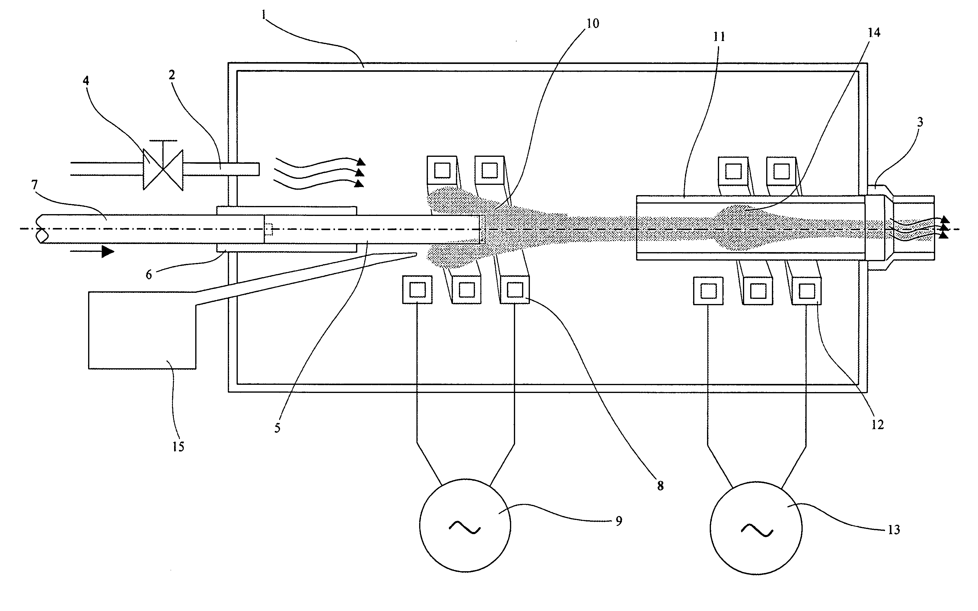
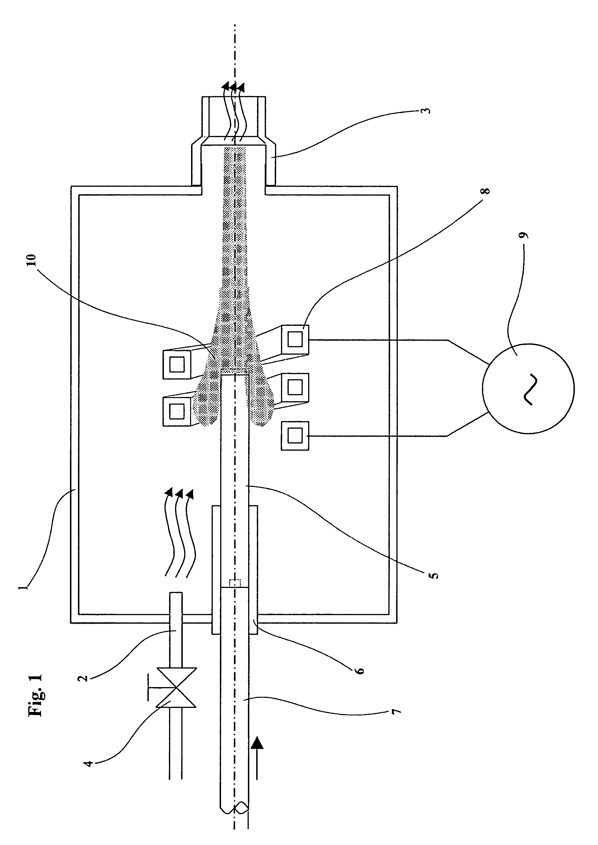
[0095]Fullerene and multi wall nanotubes were produced using the device showed in FIG. 1. As precursory material were utilized stacked up graphite rods with a purity grade not less than 99.9% and with a diameter of 6 mm.

[0096]The graphite rods were vacuum-tight inserted through a bush inside a inox steel vacuum chamber until that the head of the first rod inserted arrived near the first inductor.

[0097]After that the vacuum was made inside the chamber (vacuum limit reached 1 Pascal) inert gas argon was admitted until to arrive at a fixed pressure value inside the chamber of 50.000 Pascal with an inert gas flow of 20 l / min.

[0098]For the graphite rod continuous vaporization it was utilized the electromagnetic field generated from an inductor with length 27 mm, internal diameter 16 mm, with 4 insulated coils made of electrolytic copper tube (tube side of 6 mm and thickness of 1 mm, cooling inside by demineralized water).

[0099]This inductor was supplied from a high frequency generator, e...

example 2

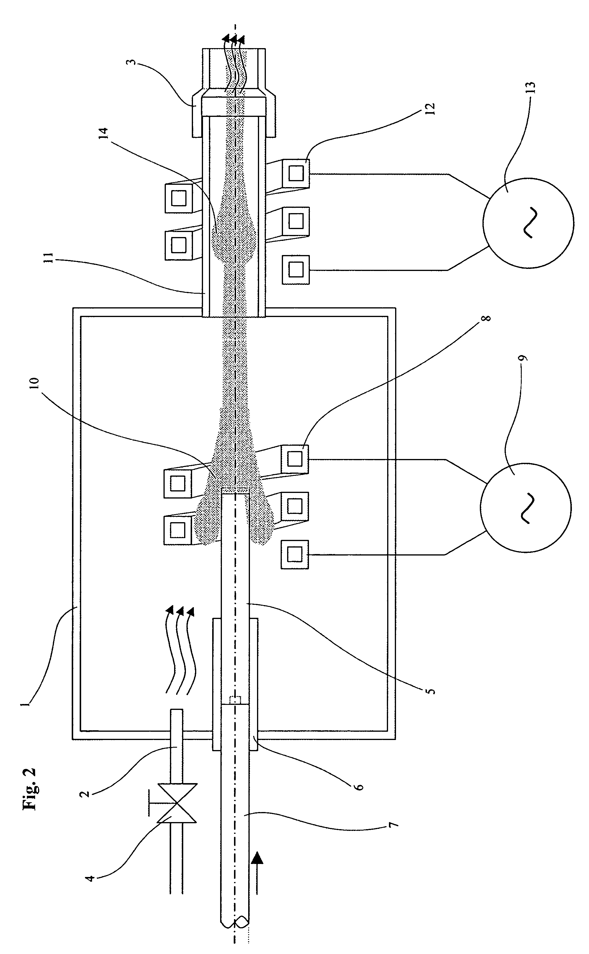
[0104]Single wall nanotubes were made using the device showed in FIG. 2 where a second inductive plasma was generated with a second inductor. The process realized in this second example was absolutely the same described in the example 1 with the only following exceptions: i) it was utilized a second inductor, made of electrolytic round copper pipe, external diameter of 10 mm and thickness of 1 mm, cooled inside by demineralized water; this second inductor was long 50 mm, made with 3 coils with internal diameter 50 mm supplied from a high frequency generator working at about 10.5 MHz; the inductor was placed coaxially to a silicon nitride tube with an external diameter of 40 mm and a thickness of 4 mm cooled by distilled water;

[0105]ii) graphite rods as those utilized in the example 1 were used but in this case the graphite rods were drilled along the axis and the holes filled with a mixture of catalysts and graphite powder subsequently compacted.

[0106]Catalysts metals used were coba...

example 3

[0109]Fullerene derivatives and fullerene were produced using the device showed in FIG. 1 with the same parameters described in the example 1. In this case the only difference respect to the example 1 was the precursory material used.

[0110]As precursory material were used graphite rods with purity grade not less than 99.9% with a diameter of 6 mm, previously submerged in distilled water for a period of 24 hours.


PUM

PropertyMeasurementUnit
poweraaaaaaaaaa
frequencyaaaaaaaaaa
temperaturesaaaaaaaaaa

Abstract

An apparatus and method for the production of nanotubes, fullerene and their derivatives where, in an environment where an inert gas flows at or below atmospheric pressure, a high frequency electromagnetic field is generated and a pure or doped graphite element is subjected to the electromagnetic field and heated to vaporization to form a plasma.

Description

FIELD OF INVENTION[0001]The present invention relates to device and method for producing carbon nanotubes, fullerene and their derivatives by continuous vaporization of substantially pure graphite rods, doped graphite rods or graphite rods compounded with other substances, in case injected in the vaporization zone.BACKGROUND OF THE INVENTION[0002]Since their recent discover and because of their unique structures and peculiar chemical-physical properties, carbon nanotubes, fullerene and their derivatives have been object of many studies and researches that demonstrated their profitable and innovative applications in many fields.[0003]The main applications of these new nanomaterials could be: realization of structural materials with unique mechanical characteristics; production of nano-metric devices (nano-motor, nano-transistor, etc.); as additive for polymers; production of Field Emission Device, (flat panels for high resolution electronic displays); as “vehicles” for pharmaceutical...

Claims


Application Information

Patent Timeline
Patent Type & Authority Patents(United States)
IPC IPC(8): B01J19/08C01B31/02
CPCB01J19/088B82Y30/00B82Y40/00C01B31/0213C01B31/0233B01J2219/0828B01J2219/0839B01J2219/0871B01J2219/0886B01J2219/0892B01J2219/0894C01B2202/02C01B2202/06C01B32/162C01B32/154
Inventor MAURO, SCHIAVON
Owner CARBONIUM
Why Eureka
Try Eureka