Fuel cell and fuel cell stack

Inactive Publication Date: 2006-10-24
HONDA MOTOR CO LTD
View PDF10 Cites 3 Cited by
  • Summary
  • Abstract
  • Description
  • Claims
  • Application Information

AI Technical Summary

Benefits of technology

[0019]A general object of the present invention is to provide a fuel cell and a fuel cell stack h

Problems solved by technology

However, the electrolyte membrane of the stabilized zirconia can not be very thin for maintaining the sufficient mechanical strength.
Therefore, it is difficult to produce a large electricity using the membrane of stabilized zirconia in the solid oxide fuel cell.
The sealing structures are considerably complicated in the fuel cell system.
Therefore, the overall fuel cell system is consider

Method used


Image

  • Fuel cell and fuel cell stack
  • Fuel cell and fuel cell stack
  • Fuel cell and fuel cell stack

Examples


first embodiment

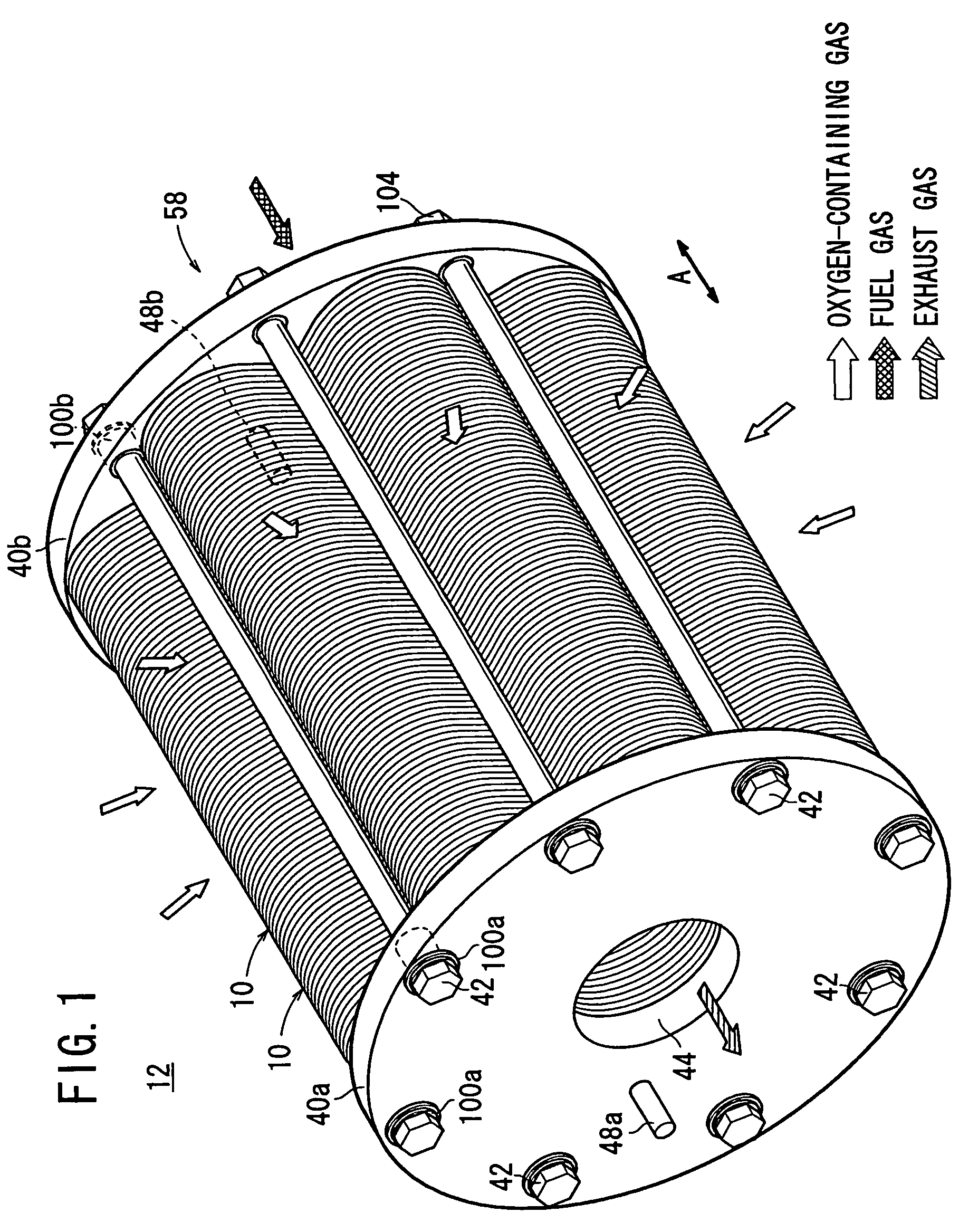
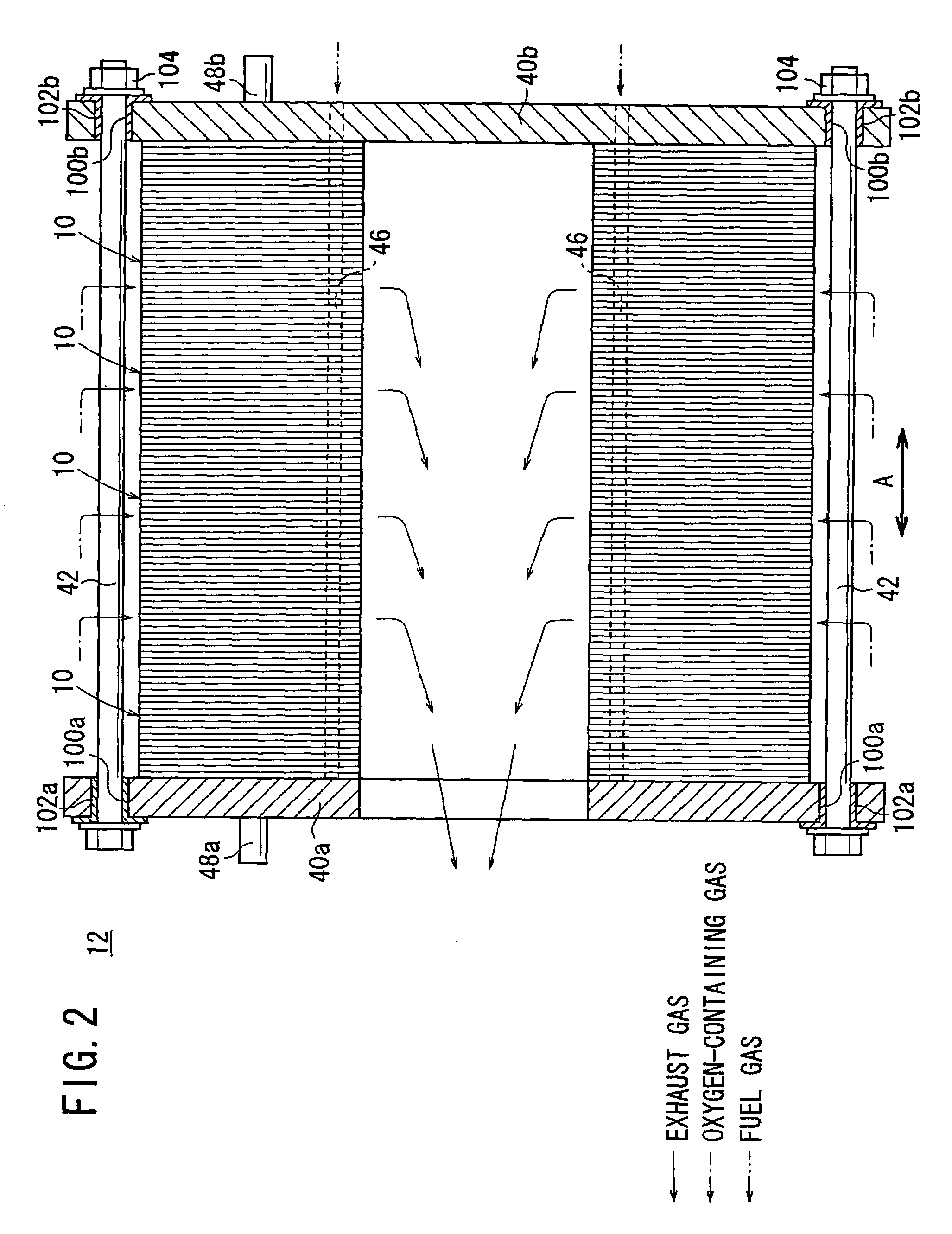
[0069]FIG. 1 is a perspective view schematically showing a fuel cell stack 12 formed by stacking a plurality of fuel cells 10 according to the present invention, and FIG. 2 is a cross sectional view showing a part of the fuel cell stack 12.

[0070]The fuel cell 10 is a solid oxide fuel cell (SOFC) for stationary and mobile applications. For example, the fuel cell 10 is mounted on vehicles. In an example of the first embodiment shown in FIG. 3, the fuel cell stack 12 is used in a gas turbine 14. In FIG. 3, the shape of the fuel cell stack 12 is different from those shown in FIGS. 1 and 2, however, the structure is substantially the same. The fuel cell stack 12 is disposed in a casing 16 of the gas turbine 14. A combustor 18 is disposed at the center of the fuel cell stack 12. The fuel cell stack 12 discharges an exhaust gas as a mixed gas of a fuel gas and an oxygen-containing gas after reaction into a chamber 20 toward the combustor 18. The chamber 20 is narrowed in a flowing directio...

second embodiment

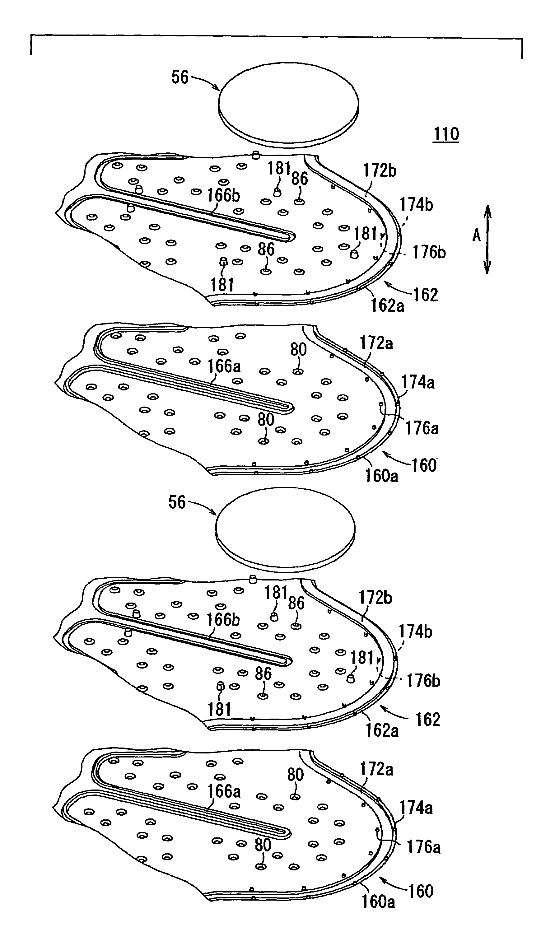
[0141]As shown in FIGS. 17 and 22, in the second embodiment, for positioning each of the electrolyte electrode assemblies 56, three protrusions 181 are formed integrally from the plate 162 of the separator 158. Therefore, the electrolyte electrode assembly 56 can be positioned accurately at a desired position simply by placing the electrolyte electrode assembly 56 inside the three protrusions 181.

[0142]As described above, the positioning of the electrolyte electrode assemblies 56 between the separators 158 can be performed with a high degree of accuracy. Therefore, the assembling efficiency of the fuel cells 110 can be greatly improved. Further, the improvement of the accuracy in positioning the electrolyte electrode assemblies 56 enables the fuel gas and the oxygen-containing gas to be supplied to the centers of the electrolyte electrode assemblies accurately. Thus, the power generation performance of the fuel cells 110 is improved desirably.

[0143]Further, the electrolyte electrode...

third embodiment

[0147]FIG. 23 is a cross sectional view schematically showing a gas turbine 190 including relatively large fuel cell stacks 112a according to the present invention, and FIG. 24 is a front view showing the gas turbine 190.

[0148]In the gas turbine 190, four fuel cell stacks 112a are arranged along a first circle in the casing 192 at intervals of 90° and four fuel cell stacks 112a are arranged along a second circle in the casing 192 at intervals of 90°. The first circle is spaced from the second circle at a predetermined distance in an axial direction of the casing 192 indicated by an arrow X. Orientation of the four fuel cell stacks 112a arranged along the first circle is shifted by 45° from the second fuel cell stacks 112a arranged along the second circle. Therefore, the fuel cell stacks 112a do not contact with each other. Each of the fuel cell stacks 112a is covered by a cover 194, and a hot air supply passage 196 is formed inside the cover 194.

[0149]In the gas turbine 190, the fou...


PUM


Abstract

A fuel cell includes a pair of separators and a plurality of electrolyte electrode assemblies between the separators. The electrolyte electrode assemblies has a small circular disk shape. Eight electrolyte electrode assemblies are arranged along an inner circle and eight electrolyte electrode assemblies are arranged along an outer circle concentric with a circular hole. Each of the separators includes a plurality of plates stacked together. A fuel gas channel for supplying a fuel gas to anodes of the electrolyte electrode assemblies, an oxygen-containing gas channel for supplying an oxygen-containing gas to cathodes of the electrolyte electrode assemblies are formed between the plates.

Description

BACKGROUND OF THE INVENTION[0001]1. Field of the Invention[0002]The present invention relates to a fuel cell having circular disk-shaped electrolyte electrode assemblies interposed between separators. Each of the electrolyte electrode assemblies includes an anode, and a cathode, and an electrolyte interposed between the anode and the cathode. Further, the present invention also relates to a fuel cell stack formed by stacking a plurality of such fuel cells.[0003]2. Description of the Related Art[0004]Typically, a solid oxide fuel cell (SOFC) employs an electrolyte of ion-conductive solid oxide such as stabilized zirconia. The electrolyte is interposed between an anode and a cathode to form an electrolyte electrode assembly. The electrolyte electrode assembly is interposed between separators (bipolar plates), and the electrolyte electrode assembly and the separators make up a unit of fuel cell for generating electricity. A predetermined number of fuel cells are stacked together to for...

Claims


Application Information

Patent Timeline
IPC IPC(8): H01M8/10H01M2/00H01M2/14H01M8/02H01M8/04H01M8/12H01M8/24
CPCH01M8/0247H01M8/0271H01M8/2425H01M8/2465H01M8/04089Y02E60/50H01M8/0258H01M8/2432H01M8/2483H01M8/02H01M8/12
Inventor TSUNODA, TADASHI
Owner HONDA MOTOR CO LTD
Why Eureka
Try Eureka