Wireless communication and control system

a control system and communication technology, applied in the field of wireless communication and control systems, can solve the problems of inability to clearly define the address hierarchy, difficult to cope with people with physical disabilities in a domestic environment, and inability to take for granted actions able-bodied people take for granted, such as turning on or off lights or answering the telephone, for a great many physically disabled peopl

Inactive Publication Date: 2006-10-24
SRS TECH
View PDF12 Cites 46 Cited by
  • Summary
  • Abstract
  • Description
  • Claims
  • Application Information

AI Technical Summary

Benefits of technology

[0017]The principal advantage of the above arrangement is that the control unit, or module sending a control signal, does not need to know the I.D. code or locati...

Problems solved by technology

This means that the list has to be copied and updated in each controller and there is no clear hierarchy of addresses to allow straightforward overall control of groups of devices in a domain.
In addition, people with physical disabilities often have great difficulty coping within a domestic environment.
Actions able-bodied people take for granted, such as turning on or off a light or answering the telephone, are impossible for a great many physically disabled people.
Hiring a carer is costly and, unfortunately, tends to result in the disable person having little say in how their house is run as the carer or relative tends to adopt set routines and controls the environment as they think best.
This is particularly evident when the disabled person has limited verbal skills.
However, many physically disabled people are capable of managing with only limited assistance from a carer, such as at bathtimes and mealtimes, if they are provided with a suitable control system which allows them to operate standard domestic appliances.
Control systems such as the one described above have a number of disadvantages: they require extensive wiring on installation which makes them difficult to retrofit into a new home; the presence of an input station in each room and the size of...

Method used


Image

  • Wireless communication and control system
  • Wireless communication and control system
  • Wireless communication and control system

Examples


Embodiment Construction

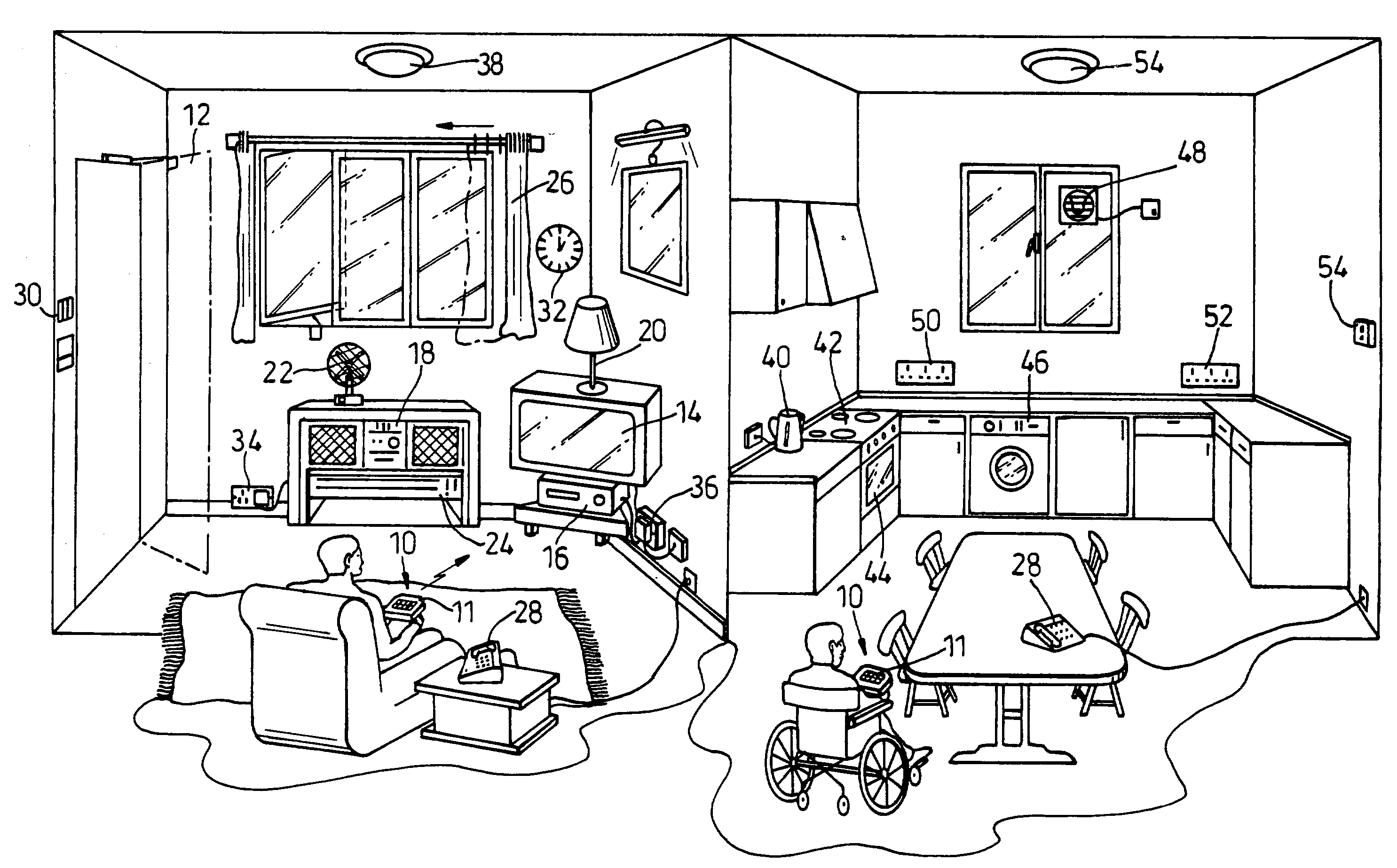
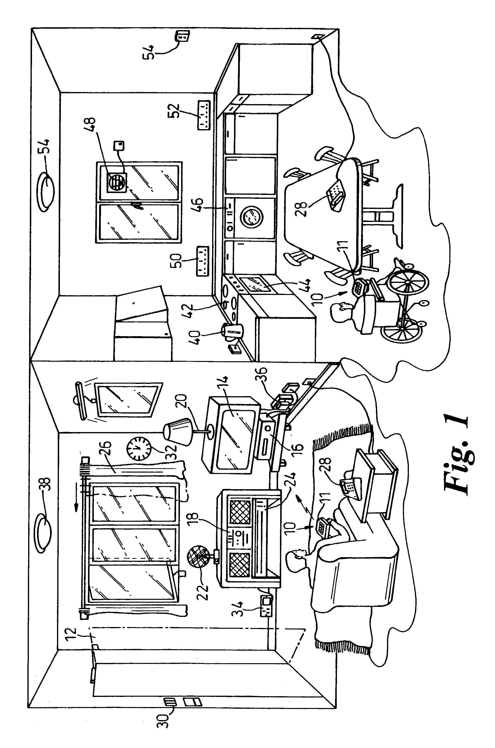
[0093]Reference is first made to FIG. 1 of the drawings which depicts a perspective view of part of two rooms in a house fitted with communications modules and a control system for operating a variety of appliances and devices in accordance with an embodiment of the present invention.

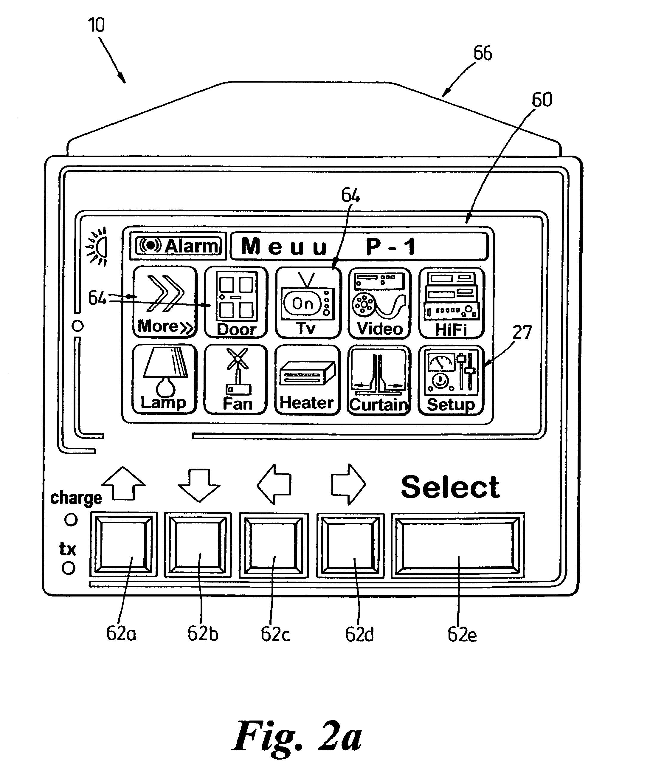
[0094]In the left room shown in FIG. 1, the lounge, a seated user has a control unit, generally indicated by reference numeral 10, in his lap. The control unit has a keypad 11 which allows the user to generate control signals for controlling a variety of items, such as a door 12, a television 14, a VCR 16, a HiFi 18, a lamp 20, a fan 22, a heater 24, curtains 26, a telephone 28, a room intercom 30, a clock 32, sockets 34,36 and a room light 38.

[0095]The rightmost picture of FIG. 1 shows a wheelchair seated user with a control unit 10 in his lap for controlling a variety of appliances in a kitchen, such as the telephone 28, a kettle 40, a cooker 42, oven 44, a washing machine 46, an extractor fan 48, wor...


PUM


Abstract

A communication and control system for use by the disabled and their caretakers. The system has at least two communication modules, each module having a processing unit which has a unique identification code. Each communication module also has a unique hierarchical address corresponding to the identification code, the address defining the physical location of the module. The hierarchical address represents at least two physical domains. Each commnunication module further includes a processing unit having coupled to it one or both of a signal receiver and a signal transmitter, and at least one transducer for detecting a physical parameter and for broadcasting packets of data indicative of the status of a module or for controlling a remote module.

Description

FIELD OF THE INVENTION[0001]The present invention relates to a wireless communication and control system particularly, but not exclusively, for use in a domestic environment to allow a user at one location to operate equipment at a remote location. The invention particularly relates to a wireless communication and control system for use by the disabled, and carers for the disabled, in a domestic environment.BACKGROUND OF THE INVENTION [0002]In many situations it is desirable for a user to control equipment or appliances remotely from a control unit which may be hardwired or wireless. This already exists with infrared (IR) controls for TV / video, HiFi and the like. In a domestic environment it is also desirable to control the operation of other items, such as lights, curtains, doors and heaters. Various systems have been proposed such as X10 (X10 Powerhouse, U.S.A.)[0003]Such systems generally have codes which require that each device has an unique code and the control unit has a list...

Claims


Application Information

Patent Timeline
IPC IPC(8): H04M1/00G08C17/02G08C23/04G08C25/02
CPCG08C17/02G08C23/04G08C25/02G08C2201/31G08C2201/51G08C2201/92H05B47/12Y02B20/40
Inventor SINCLAIR, JOHN
Owner SRS TECH
Why Eureka
Try Eureka