
Method and system for satellite using multifunctional motherboard

a multi-functional motherboard and satellite technology, applied in the field of satellite circuitry, can solve the problems of increasing the cost of launch substantially, adding the weight of cables, and adding to the cost of making and launching satellites, so as to avoid unnecessary weight in satellites

Active Publication Date: 2018-05-01
L3 TECH INC
View PDF28 Cites 0 Cited by
  • Summary
  • Abstract
  • Description
  • Claims
  • Application Information

AI Technical Summary

Benefits of technology

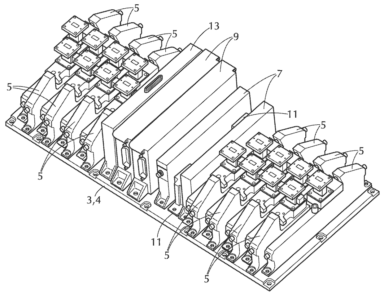
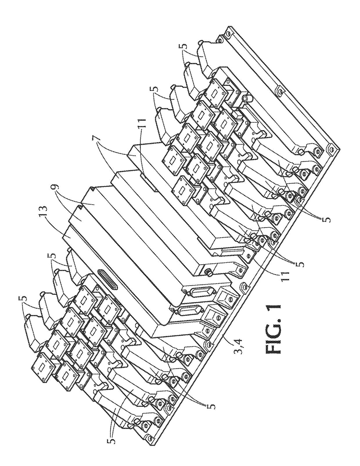
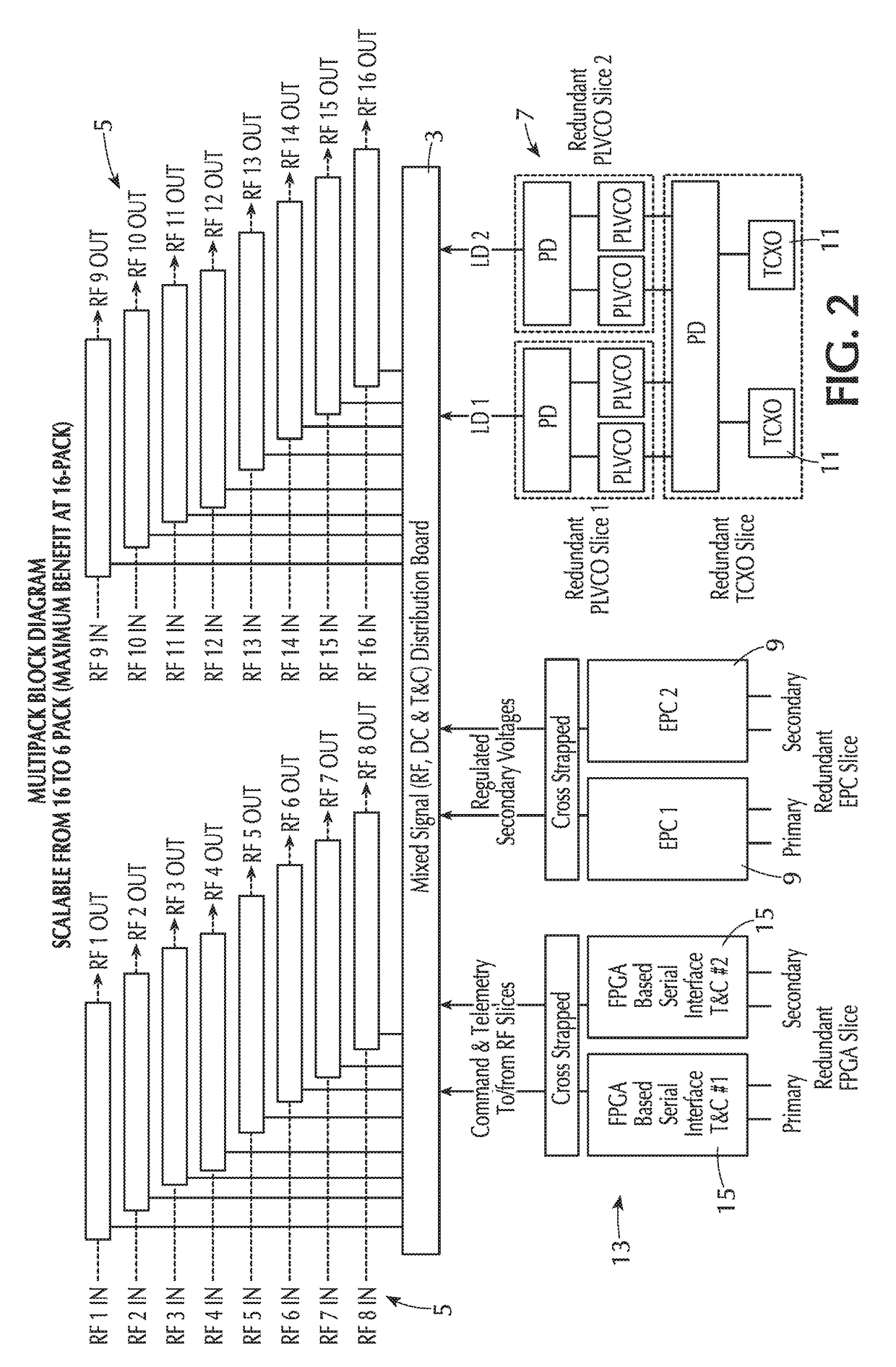
The present invention provides an arrangement for two or more mixers or frequency converters that avoids unnecessary weight in the satellite. It also allows for relatively simple and reliable assembly of the operational components of a satellite's electronic payload. The mass of the entire system of frequency converters is reduced by placement of the converters on a shared circuit board. The board supporting the components is an underlying multilayer motherboard on which a set constituting some or all of the satellite frequency converters are mounted. This reduces the number of LO sources and power supplies needed, and, as a consequence, weight of the satellite is reduced. Additionally, an additional redundant LO source and an additional redundant power supply may be provided in parallel to the frequency converters of the set to ensure uninterrupted operation of the satellite.

Problems solved by technology

The number of power supplies and LO sources contributes to the weight of the satellite, which is highly undesirable, as even relatively slight additional weight of a satellite increases the cost of launch substantially.
The cables add to weight of the satellite, and the cable arrangement complicates assembly of the satellite from its components, which also adds to the cost of making and launching the satellite.

Method used


Image

  • Method and system for satellite using multifunctional motherboard
  • Method and system for satellite using multifunctional motherboard
  • Method and system for satellite using multifunctional motherboard

Examples


Embodiment Construction

[0038]The present invention relates to an apparatus used in a satellite in which integrated frequency converters or low-noise amplifiers that share common resources, i.e., local oscillator and power supply units, are supported on a multilayer motherboard structure carrying multiple signals to the integrated set of frequency converters or low-noise amplifiers in a multipack architecture. Such a satellite is schematically illustrated in FIG. 14. Generally, the satellite in orbit receives wireless RF transmissions from the earth with a receiving antenna or antennae, converts them to a different frequency range, and retransmits the converted signals back to earth via a transmission antenna or antennae.

[0039]All functionalities of multipack, frequency conversion, DC conversion, local oscillation (LO) signal generation, and telecommand and telemetry interfacing are integrated in a single mechanical package. All the signals and power necessary to operate the receiver units in the integrate...


PUM


Abstract

A satellite is configured for use in space so as to receive RF signals, convert them to a different frequency range, and retransmit the converted RF signals. The satellite comprises a payload area supporting a motherboard structure with a plurality of frequency converters supported on it. The frequency converters are each connected with an antenna system of the satellite so that each of them receives a respective RF input signal. A local oscillator source supported on said motherboard structure generates a local oscillator signal, and a motherboard in the motherboard structure receives the local oscillator signal and transmits it through the motherboard to each of the frequency converters. The frequency converters each convert the respective RF input signal to a respective RF output signal using the local oscillator signal and transmit the RF output signal to the antenna system so as to be transmitted wirelessly.

Description

FIELD OF THE INVENTION[0001]This invention relates to the general field of circuitry for use in satellites, and more particularly to systems for use in satellites supporting multiple frequency converters or other similar components.BACKGROUND OF THE INVENTION[0002]As is well known, satellites commonly are used to receive RF signals at one frequency that contain data (which would include TV signals, audio signals, and any other sort of data or information stream) from the earth, to then convert the RF signal received to a second RF signal of a different frequency containing the data, and to then transmit the second RF signal back to the earth.[0003]The change of frequency is accomplished using mixers or frequency converters on the satellite that are configured to receive an RF signal at one predetermined frequency and combine it with a local oscillator (LO) signal at another frequency to output a second RF signal derived from it at a second different frequency. Each frequency convert...

Claims


Application Information

Patent Timeline
Patent Type & Authority Patents(United States)
IPC IPC(8): H04B7/185H04W4/00H05K1/02
CPCH05K1/0243H04B7/18515H05K3/3452
Inventor RALPH, LOREN EDWARDRODGERS, EDDIEROBERSON, JAMES H.
Owner L3 TECH INC
Learn More