
Methods and apparatus for homogenizing molten glass

a technology of molten glass and homogenization method, which is applied in the direction of manufacturing tools, instruments, transportation and packaging, etc., can solve the problems of individual difficulty in seeing on a microscopic scale, increased cutting frequency, and potential dispersion rate, and designed to produce high shear stress

Active Publication Date: 2006-10-31
CORNING INC
View PDF23 Cites 37 Cited by
  • Summary
  • Abstract
  • Description
  • Claims
  • Application Information

AI Technical Summary

Benefits of technology

[0030]A preferred application for each of the above three aspects of the invention is in the manufacture of liquid crystal display glass. When used in this application, t

Problems solved by technology

Making the streaks thin and cutting them makes them individually difficult to see on a microscopic scale.
This increases the shear stress, the cutting frequency, and potentially also the dispersion rate.
Indeed, such systems are normally designed to produce high shear stress even when operated at low speeds.
The intent is to get the most stirring from the smallest stirring system because of the high cost of the precious metals (e.g., platinum alloys) from which the stirring system is fabricated.
These latter objects and the primary object pull in opposite directions, e.g., one can reduce stirrer speed to reduce sheer stress and thus erosion, but reduced stirrer speed means less efficient stirring and / or reduced throughput.

Method used


Image

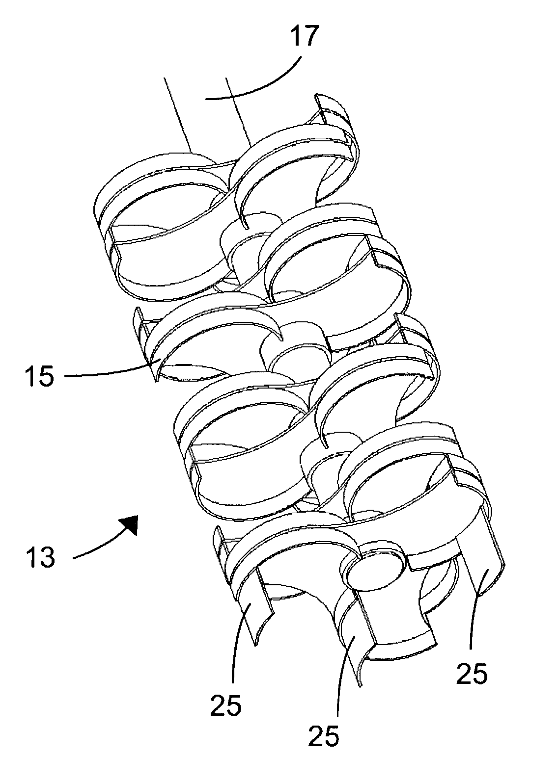
  • Methods and apparatus for homogenizing molten glass
  • Methods and apparatus for homogenizing molten glass
  • Methods and apparatus for homogenizing molten glass

Examples


example 1

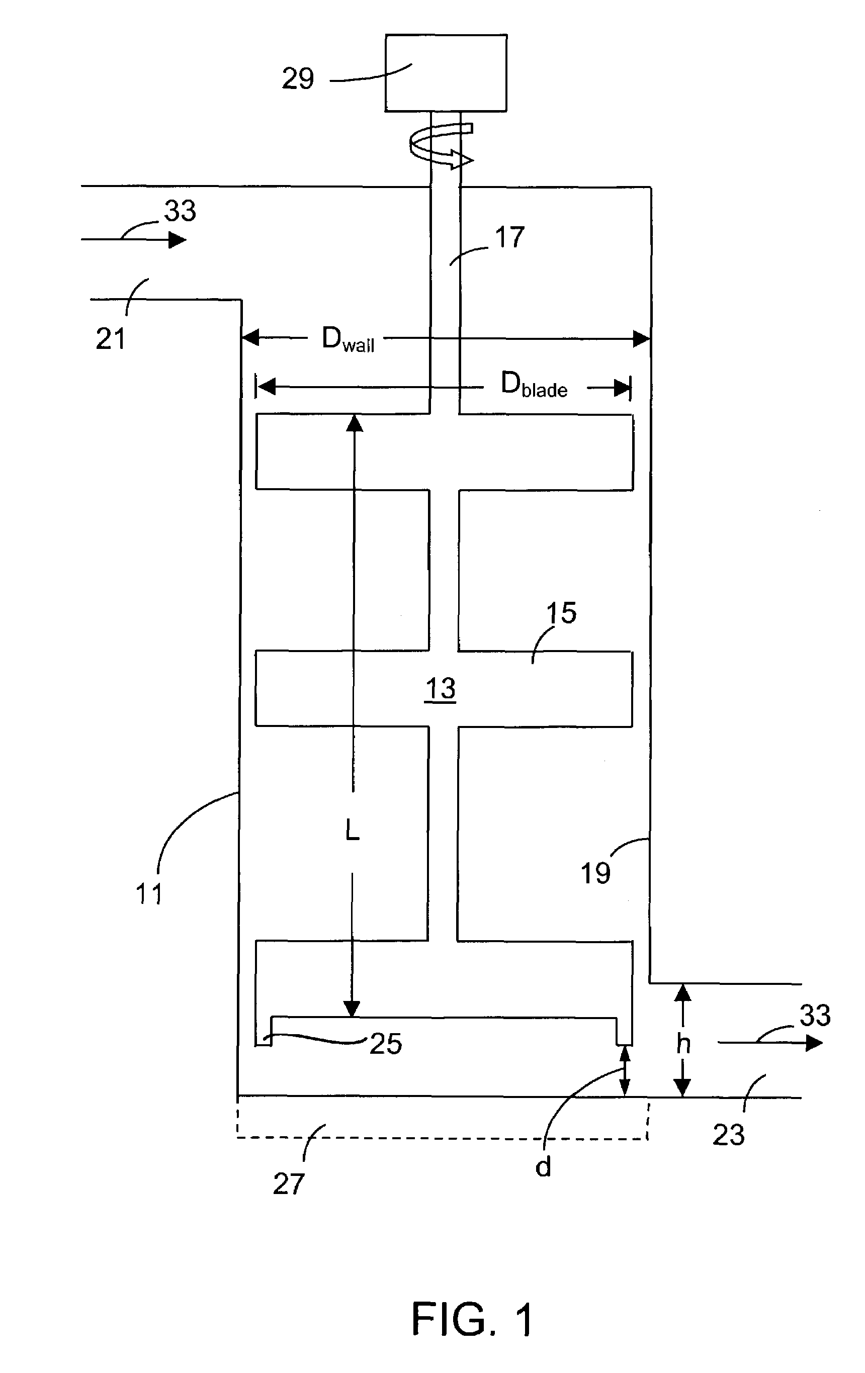
[0072]As an example of the application of the concepts discussed above, Table 1 compares two stirring systems, the first being representative of previously used stirring systems (e.g., a stirring system having a blade diameter of 6 inches, a glass viscosity of 3000 poise, and a stirrer rotational speed of 30 rpm), and the second one being representative of a stirring system designed in accordance with the invention (e.g., a stirring system having a diameter of 10 inches, a glass viscosity of 1000 poise (achieved by increasing the temperature of the molten glass by, for example, approximately 80° C.), and a stirrer rotational speed of 6.3 rpm).

[0073]As can be seen in this table, the shear stress on the stirrer can be reduced almost by an order of magnitude by increasing the stirrer diameter from 6″ to 10″ and reducing the stirred glass viscosity from 3000 to 1000 poise. These changes allow a stirrer speed reduction by a factor of four. A useful byproduct is that the torsional stress ...

example 2

[0074]FIGS. 6 and 7 show comparisons between historical stirring (diamond data points) and stirring performed in accordance with the present invention (square data points). The data was obtained using actual production equipment. In all cases, stirring was performed using a substantially vertically-oriented stir chamber and a substantially non-pumping stirrer having a substantially vertically-oriented shaft.

[0075]The straight line of FIG. 6, which is a fit to the historical data, shows that prior to the present invention, high Q•E products were only achieved through the use of high levels of shear stress. Conversely, low levels of shear stress were only achieved with low Q•E products. In contrast, stirring in accordance with the concepts of the present invention simultaneously achieves low shear stress and high Q•E products.

[0076]The importance of low shear stress in the production of LCD glass is illustrated in FIG. 7. As shown therein, in accordance with the invention, the level o...


PUM

PropertyMeasurementUnit
Pressureaaaaaaaaaa
Sizeaaaaaaaaaa
Mass flow rateaaaaaaaaaa

Abstract

The level of precious-metal inclusions in glass products, e.g., glass substrates for liquid crystal displays, is reduced by stirring molten glass in a stir chamber (11) under conditions such that the magnitude of the shear stress τ on the chamber's wall (19) and on the surfaces of the stirrer (13) is reduced while at the same time, the Q•E product for the system is kept high, where Q is the flow of glass through the stirring system and E is the system's stirring effectiveness.

Description

FIELD OF THE INVENTION[0001]This invention relates to the homogenization of molten glass and, in particular, to the homogenization of molten glass which will be used to produce high quality finished products having low levels of defects. A particularly important application of the invention is in the manufacture of glass substrates for liquid crystal displays, such as the substrates used in the production of AMLCDs.BACKGROUND OF THE INVENTION[0002]Chemical and thermal homogeneity in glass is a crucial part of good forming operations. The function of a glass melter is generally to produce glass with acceptable levels of gaseous or solid inclusions, but this glass usually has cord (or striae or ream) of chemically dissimilar phases. These non-homogeneous components of the parent glass result from a variety of normal occurrences during the melting process including refractory dissolution, melting stratification, glass surface volatilization, and temperature differences. The resulting c...

Claims


Application Information

Patent Timeline
IPC IPC(8): C03B5/187B01F7/00G02F1/1333B01F7/16B01F15/00
CPCB01F7/00275B01F7/00466B01F7/00908C03B5/1875C03B5/187B01F2215/0409B01F2215/044B01F7/16B01F27/1123B01F27/1152B01F27/50B01F27/80B01F27/00
Inventor GOLLER, MARTIN H.MURPHY, JAMES P.NOLET, DANIEL A.THOMAS, ROBERT R.
Owner CORNING INC
Features
  • Generate Ideas
  • Intellectual Property
  • Life Sciences
  • Materials
  • Tech Scout
  • Unparalleled Data Quality
  • Higher Quality Content
  • 60% Fewer Hallucinations
Learn More