
High speed resiliometer

a resiliometer and high-speed technology, applied in the field of apparatus and methods for determining the physical properties of a material, can solve the problems of increasing the cost of material testing, increasing the time and cost of methods, etc., and achieves the effects of reducing time and cost, reducing the size of the space, and simplifying the testing process

Inactive Publication Date: 2006-10-31
ACUSHNET CO
View PDF31 Cites 8 Cited by
  • Summary
  • Abstract
  • Description
  • Claims
  • Application Information

AI Technical Summary

Benefits of technology

The present invention is an apparatus and method for testing the physical properties of a material. It uses a projectile to impact a material sample and measure the contact time and COR (cross-sectional area) of the material sample. The apparatus includes a holding device for the material sample and a propulsion device for propelling the projectile towards the material sample. The apparatus can be used with different materials and can measure resilience gradients of anisotropic materials. The apparatus is compact, efficient, and can be used with a variety of materials. The technical effects of the invention include improved accuracy and precision in testing material properties, reduced testing time and cost, and the ability to measure resilience gradients of materials.

Problems solved by technology

Due to the high rate of deformation associated with golf ball use, these testing machines involve forming a sample of a material and firing it towards a flat surface, such as an immovable plate.
Manufacturing a spherical sample of a material may require specialized molds, unique degassing equipment, or large material quantities, and thus complicates and increases the cost of material tests.
These methods are also more time consuming because they require the uniquely molded material sample to be formed according to strict specifications.
Furthermore, these testing machines require a new spherical sample to be manufactured if an existing one is deformed in any way, such as by chipping, cracking, tearing, or change in sphericity.

Method used


Image

  • High speed resiliometer
  • High speed resiliometer
  • High speed resiliometer

Examples


Embodiment Construction

[0019]Prior methods and apparatus for measuring the physical properties, such as resiliency or Coefficient of Restitution (COR) of a material, have involved large apparatus and samples that require arduous preparation. These apparatus may be used in many applications including, but not limited to, the testing of golf equipment. Apparatus for testing the COR of materials are often used in testing candidate material for golf balls. As such, prior COR testing apparatus typically require molding thermoset or thermoplastic materials into a spherical sample. These apparatus often have several drawbacks such as, for example, requiring a costly apparatus to mold the spherical sample and large volumes of sample material to produce an adequate quality and quantity of specimens. In addition, the COR testing apparatus typically requires a large area through which the spherical sample can be fired at a substantially immovable wall. Furthermore, firing spherical samples does not allow for testing...


PUM


Abstract

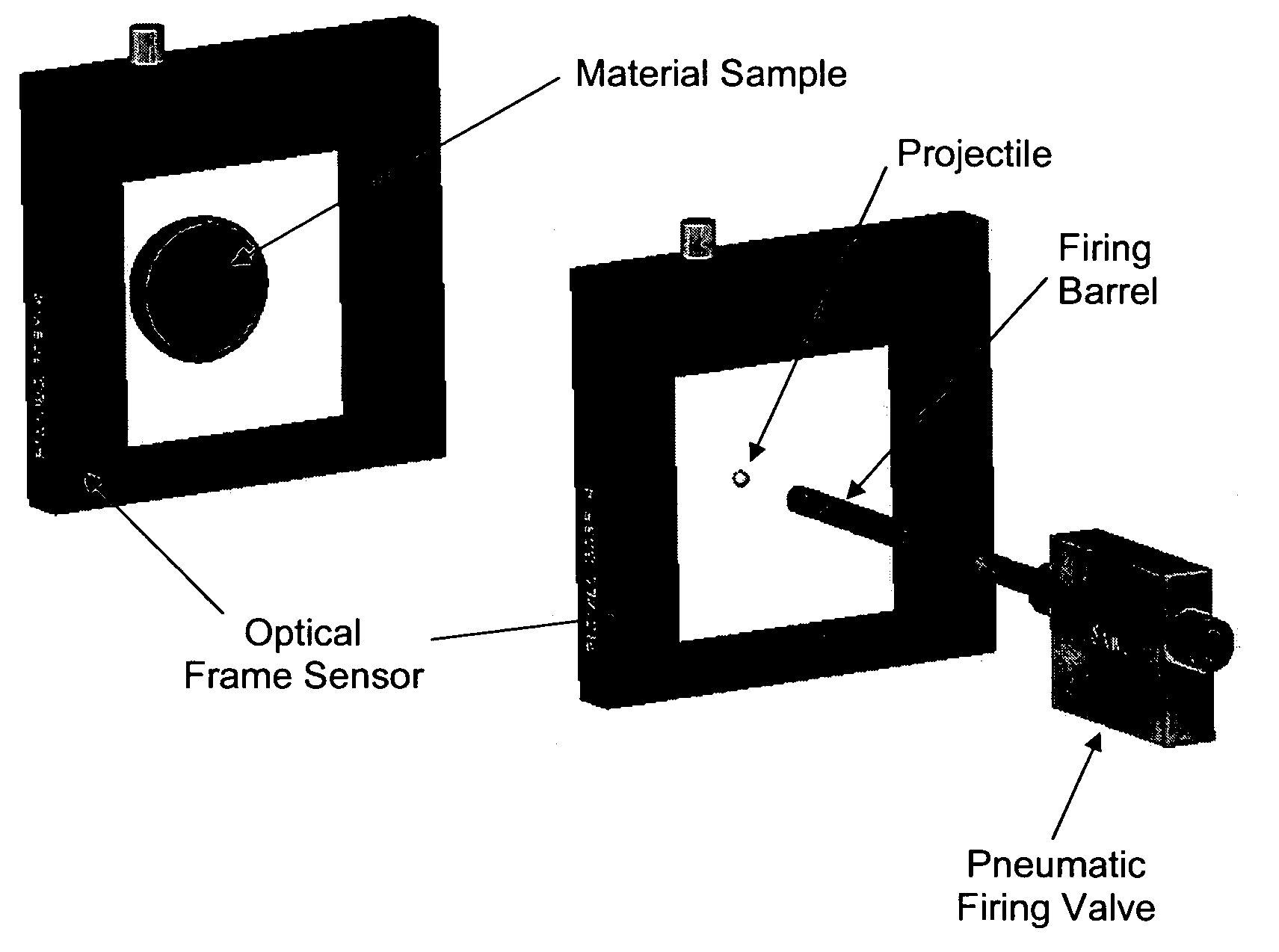
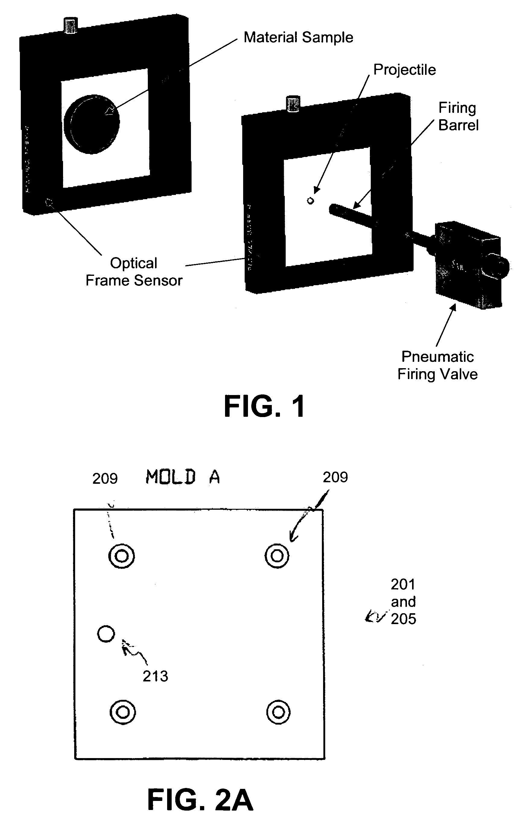
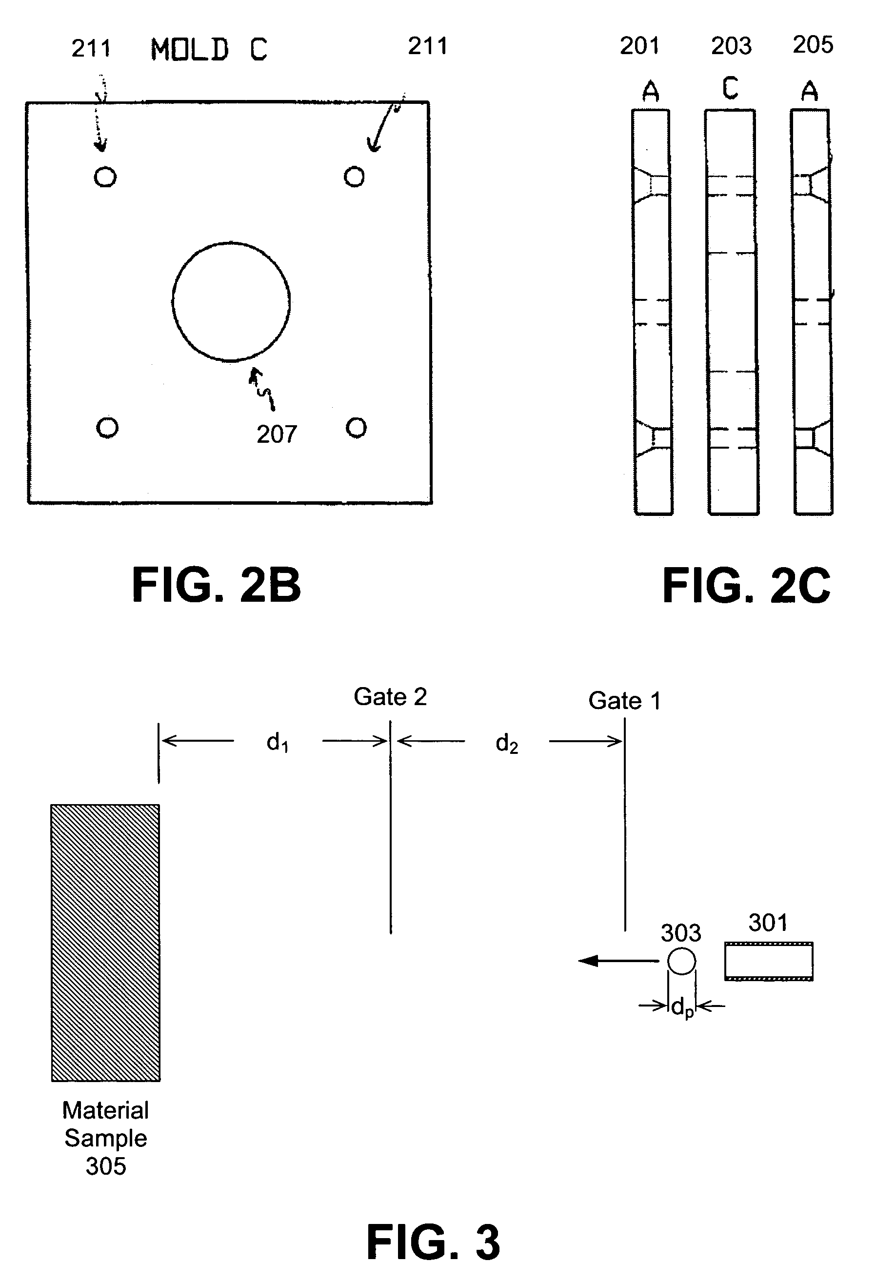
An apparatus and method for testing the physical properties of a material is disclosed. Preferably, the physical properties that may be tested include, but are not limited to, the COR of a material. Accordingly, the apparatus includes a projectile that may be capable of being propelled towards a material sample. The projectile is preferably aimed and fired through a tubular barrel towards the material sample. The tubular barrel preferably comprises a propulsion system that controls pneumatic energy via a pneumatic valve. At least two sensors are placed between the tubular barrel and the material sample in order to detect the passage of the projectile. It is desired that the sensors are placed at precise, discrete positions. As the projectile passes through the field of view of each sensor, the time is recorded to a memory, for example, a counter timer board. The projectile may then impact the material sample, which may preferably be held in place by a fixation device. The fixation device is preferably a holding slot, which may be backed by an infinite mass cylinder. Upon rebounding from the material sample, the projectile passes back through the field of view of the sensors in reverse order, allowing the sensors to capture and record the time of passage to a memory, such as a counter timer board. The physical properties of the material sample may be calculated by a processing device that is operatively connected to at least a portion of the apparatus.

Description

FIELD OF THE INVENTION[0001]The present invention relates to an apparatus and method for determining the physical properties of a material. More specifically, the present invention relates to an apparatus and method for efficiently measuring the coefficient of restitution and contact time for a collision between a projectile with known material properties and a material sample with unknown material properties.BACKGROUND OF THE INVENTION[0002]The manufacturing of golf clubs and balls requires extensive testing to determine which equipment will prove most advantageous for golf players. Many tests are performed during the designing of equipment in order to determine which materials are best suited for a particular piece of equipment, such as a club or ball. Testing the properties of a particular type of material enables designers to determine the best mode of applying these materials as well as potential product performance advantages.[0003]To determine the properties of different mate...

Claims


Application Information

Patent Timeline
Patent Type & Authority Patents(United States)
IPC IPC(8): G01M7/00
CPCG01N3/48G01N2203/001
Inventor CORREIA, DIOMARMCNAMARA, MICHAELBISSONNETTE, LAURENT C.BULPETT, DAVID A.
Owner ACUSHNET CO
Learn More