Method for controlling magnet type fan clutch

a technology of magnet-type fans and clutches, which is applied in the direction of magnetically actuated clutches, machines/engines, and road transportation, etc., can solve the problems of power loss, reduced fuel efficiency, and the inability to prevent the noise generated by unnecessary fan rotation at the acceleration time, so as to improve the cooling capacity of an air conditioner (a/c) condenser, improve engine performance and fuel efficiency, and prevent fan noise

Inactive Publication Date: 2006-10-31
USUI KOKUSAI SANGYO KAISHA LTD
View PDF6 Cites 12 Cited by
  • Summary
  • Abstract
  • Description
  • Claims
  • Application Information

AI Technical Summary

Benefits of technology

[0004]Therefore, in order to overcome the drawbacks of the above-described cooling control method which depends on the temperatures of air flowing through the radiator, the applicant of the present invention previously proposed an external control type fan clutch which is capable of improving engine performance and fuel efficiency, enhancing cooling capability of an air conditioner (A / C) condenser, and preventing fan noise produced due to fan rotation at the time of acceleration (see JP-A-2002-195303, JP-A-2003-156072 and other reference) This external control type fan clutch is provided with a magnet coupling, an electromagnetic clutch integrally combined with the magnet coupling, and a fan attached to the magnet coupling, and on / off switching of the magnet coupling is controlled by the electromagnetic clutch. More specifically, the external control type fan clutch includes, for example: a rotative electromagnetic clutch having a clutch rotor in which an exciting coil supported on both a drive shaft and an external member is incorporated and an armature attached to a disc which is rotationally supported on the drive shaft via a bearing unit; and a magnet coupling having a permanent magnet rotating member which is rotationally supported on the drive shaft via the bearing unit, a fan attached to the outer surface of the permanent magnet rotating member, and a hysteresis material or a conductor attached to the disc in such a position that the hysteresis material or the conductor is opposed to the permanent magnet leaving a small gap there between, wherein the permanent magnet rotating member and the disc rotate integrally or relatively due to suctional effect generated between the permanent magnet and the hysteresis material or the conductor. In the external control type fan clutch having this structure or other, the on / off switching of the magnet coupling can be controlled by the electromagnetic clutch.
[0005]According to the magnet type fan clutch having the structure as above, the magnet coupling, i.e., the fan rotation can be controlled through the on / off control of the electromagnetic clutch. More over, since the on / off switching of the electromagnetic clutch is controlled in association with cooling water temperatures, throttle opening, engine rotational speeds, and switch status of the air conditioner, an excellent advantage of providing accurate and stable control over the fan rotation can be offered.
[0006]It is an object of the present invention to provide a method for controlling a magnet type fan clutch, by which method engine performance, fuel efficiency, engine life, vehicle acceleration capability and other properties of such a magnet type fan clutch as previously proposed by the applicant of the present invention can be further improved and fan noise of the magnet type fan clutch can be further reduced

Problems solved by technology

However, the above-described method for controlling the viscous fluid coupling, in which the valve is opened and closed by deformation of the bimetal reacting to temperatures of air flowing through the radiator to vary the oil supply amounts and thus alter the fan rotations, has several drawbacks.
Since the temperature of engine coolant which affects the capability of cooling the engine cannot be directly controlled, the following points result: power loss caused due to unnecessary fan rotation lowers fuel efficiency; preferable fan rotation for cooling a condenser of an air conditioner (A / C) cannot be maintained; fan noise generated due to unnecessary fan rotation caused at the time of acceleration cannot be prevented and other points.

Method used


Image

  • Method for controlling magnet type fan clutch
  • Method for controlling magnet type fan clutch
  • Method for controlling magnet type fan clutch

Examples


Embodiment Construction

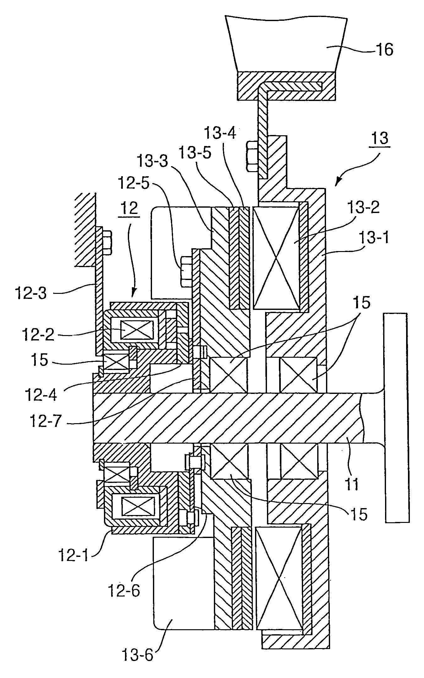
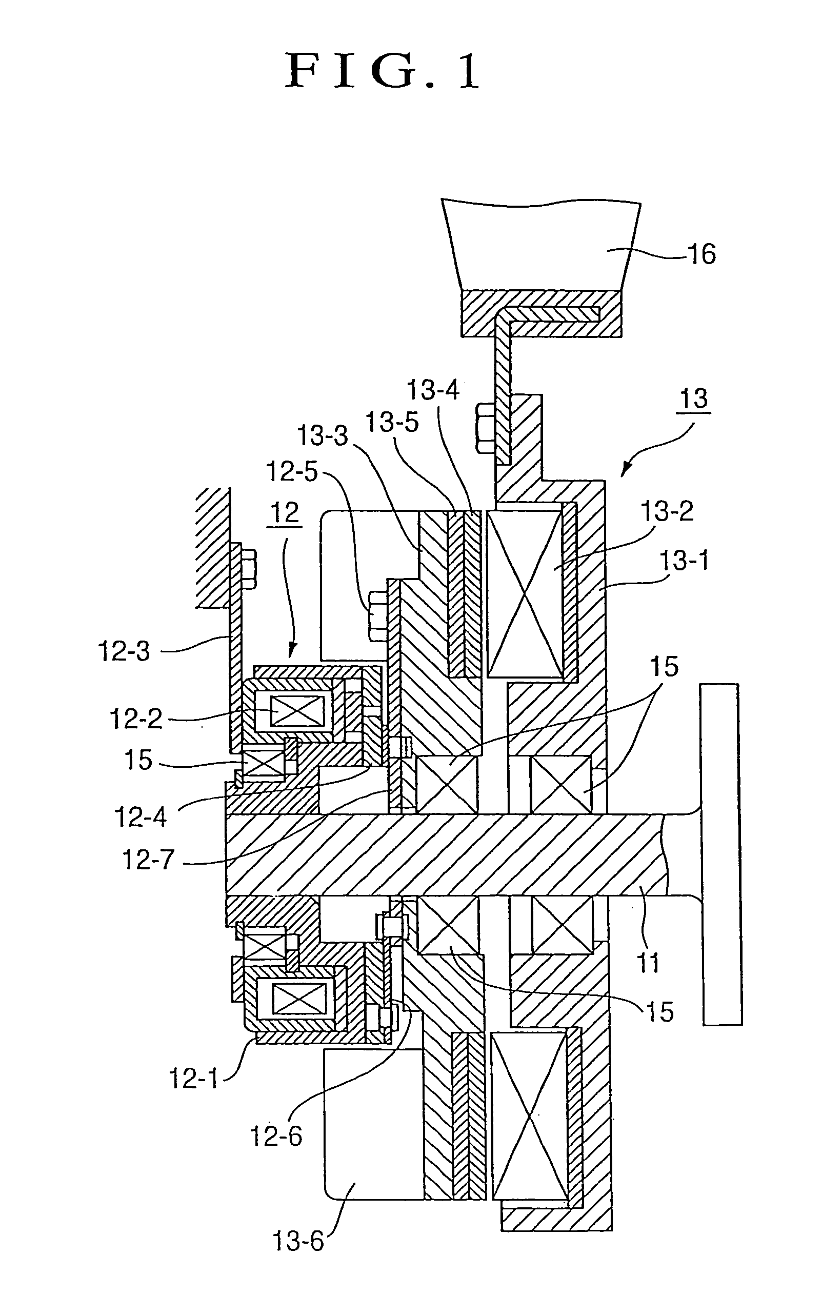
[0015]According to the present invention, a magnet type fan clutch as illustrated in FIG. 1 contains an electromagnetic clutch 12 disposed on a single drive shaft 11 and a magnetic coupling 13. The electromagnetic clutch 12 includes: a clutch rotor 12-1 integrally supported on an end of the drive shaft 11; an exciting coil 12-2 which is fitted into the clutch rotor 12-1 in such a manner as to relatively rotate via a bearing unit 15 and also is secured to an external member through a bracket 12-3; and an armature 12-4 which is movable forward and backward and supported on a disc 13-3 at the exciting coil 12-2 side. The disc 13-3 is rotationally supported on the drive shaft 11 via the bearing unit 15. The armature 12-4 is attached to the clutch rotor 12-1 through a spring 12-6 an end of which is fixed to a stay 12-7. The stay 12-7 is fitted to the outer surface of the drive shaft 11 and an end of the stay 12-7 is secured to the disc 13-3 with a bolt 12-5. As for the magnet coupling 13...


PUM


Abstract

Provided is a method for controlling a magnet type fan clutch, by which method engine performance, fuel efficiency, engine life, vehicle acceleration capability and other properties of a magnet type fan clutch can be further improved and its fan noise can be further reduced. This method is adopted for controlling a magnet type fan clutch which includes a magnet coupling, an electromagnetic clutch combined with the magnet coupling to control the on / off switching of the magnet coupling, and a fan attached to the magnet coupling. The control method is characterized in that the electromagnetic clutch is turned on or off based on at least one signal of temperatures of radiator coolant, engine oil and transmission oil, a vehicle speed, a rotational speed of an engine, compressor pressure of an air conditioner, and an on / off signal of the air conditioner, etc., so as to control the rotation of the fan.

Description

TECHNICAL FIELD[0001]The present invention relates to a method for controlling a magnet type fan clutch which rotationally controls a cooling fan chiefly employed for an internal combustion engine for a vehicle, and more particularly to a method for controlling a magnet type fan clutch in which a magnet coupling and an electromagnetic clutch are combined such that the on / off switching of the magnet coupling can be controlled by the electromagnetic clutch.BACKGROUND ART[0002]As a magnet type fan clutch which rotationally controls a cooling fan used for an internal combustion engine for a vehicle, a viscous fluid coupling which receives driving torque from a vehicle engine and transmits output driving torque to a radiator cooling fan and a method for controlling the viscous fluid coupling have been disclosed (see JP-A-9-119455). According to a mechanism of the viscous fluid coupling, a valve is opened and closed by deformation of bimetal which reacts to temperatures of air flowing thr...

Claims


Application Information

Patent Timeline
Patent Type & Authority Patents(United States)
IPC IPC(8): B60W10/02F16D27/01F01P7/08F16D27/112F16D27/12F16D48/06
CPCF16D27/112F16D48/064Y10T477/76F16D2500/1022F16D2500/10418F16D2500/1045F16D2500/3067F16D2500/30803F16D2500/3108F16D2500/3144F16D2500/31493F16D2500/70424Y02T10/76Y10T477/78Y10T477/755Y10T477/753F16D27/12
Inventor INOUE, HIROSHISHIOZAKI, KEN
Owner USUI KOKUSAI SANGYO KAISHA LTD
Why Eureka
Try Eureka