Low-energy storage fast-start uninterruptible power supply method

Inactive Publication Date: 2006-10-31
ABB (SCHWEIZ) AG
View PDF40 Cites 50 Cited by
  • Summary
  • Abstract
  • Description
  • Claims
  • Application Information

AI Technical Summary

Benefits of technology

[0008]In another exemplary embodiment of the present invention, a method of operating an uninterruptible power supply system is provided comprising the steps of operating the system in a standby mode by maintaining the system electrically connected to a power grid in a state of readiness to change to a backup mode in response to detecting a fault in the power

Problems solved by technology

Present day computer data centers and internet service providers require highly reliable sources of uninterruptible power.
A problem exists, however, in that conventional engine driven alternator UPS systems with 100 k

Method used


Image

  • Low-energy storage fast-start uninterruptible power supply method
  • Low-energy storage fast-start uninterruptible power supply method
  • Low-energy storage fast-start uninterruptible power supply method

Examples


Embodiment Construction

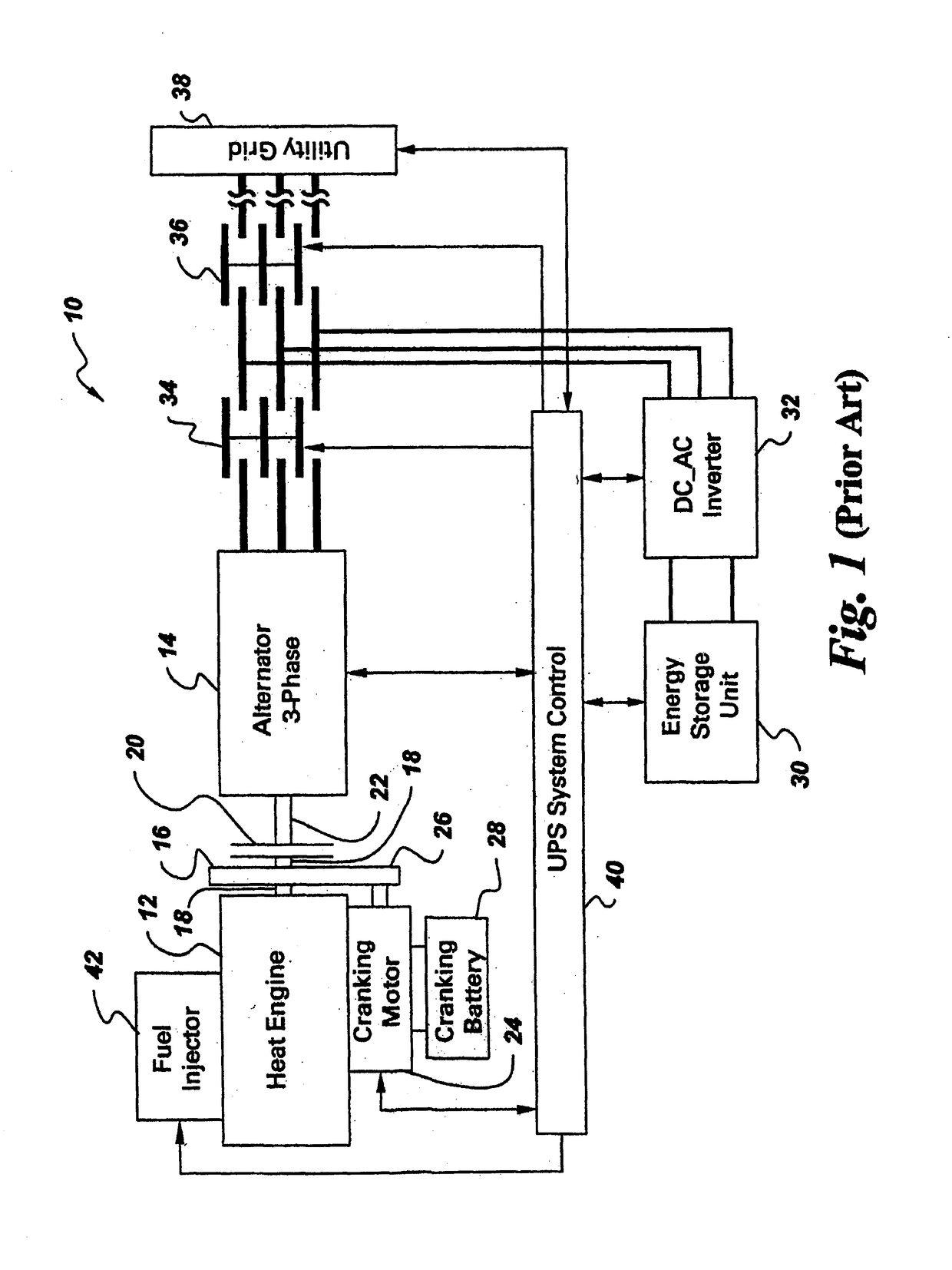
[0012]Referring now to the drawings and particularly to FIG. 1, there is illustrated a prior art uninterruptible power supply (UPS) system, generally designated 10. The prior art UPS system 10 of FIG. 1 includes a heat engine 12, an alternator 14, a flywheel 16 mounted on a crankshaft 18 of the heat engine 12, a motion transmitting mechanism 20 disposed between the flywheel 16 and an alternator input shaft 22 and actuatable for coupling the flywheel to and from the input shaft 22 of the alternator 14, a starter or cranking motor 24, gearing 26 drivingly coupling the cranking motor 24 to the flywheel 16 and a cranking battery 28 connected to the cranking motor 24. The cranking battery 28, for example, can be a 12V or 24V battery.

[0013]The prior art UPS system 10 also includes an energy storage unit 30, a DC-AC inverter 32 connected to the energy storage unit 30, and first and second transfer switches 34, 36, such as 3-phase contactors. The transfer switches 34, 36 are operable for co...


PUM


Abstract

An uninterruptible power supply system has standby and backup modes and can change to backup mode upon detection of a grid fault. In both modes an alternator rotates at synchronous speed so that backup mode capability is ready. An energy storage unit through a DC-AC inverter remains coupled to the grid in standby mode so that it is charged, ready to supply power when changed to backup mode. In standby mode, first and third clutches are disengaged and engaged, transmitting alternator rotary motion to a flywheel but not therefrom to a heat engine. In backup mode, first and third clutch are engaged and disengaged to permit the alternator, via a second clutch, to overrun the flywheel and allow transmitting of flywheel torque to accelerate the heat engine to starting speed for driving the alternator to supply power to the grid after the engine is at operating speed and coupled to the alternator through a locked second clutch and an engaged third clutch.

Description

[0001]This is a Divisional application Ser. No. 09 / 681,697 filed May 23, 2001 now U.S. Pat. No. 6,507,128.BACKGROUND OF INVENTION[0002]The present invention generally relates to a backup system for a utility power grid and, more particularly, is concerned with an uninterruptible power supply (UPS) system and method having a fast-start capability and a low-energy storage requirement.[0003]Present day computer data centers and internet service providers require highly reliable sources of uninterruptible power. Dual fed utility grid systems plus uninterruptible power supplies with back-up generation are utilized to meet the stringent demands for critical power. A conventional UPS system normally includes a DC-AC inverter, transfer switches, an energy storage unit, oftentimes using massive lead acid batteries, and, in many cases, an alternator driven by a heat engine. During a fault in the dual-fed grid source, DC power from the energy storage unit (usually batteries) is converted to th...

Claims


Application Information

Patent Timeline
IPC IPC(8): F02D25/00H02J7/00H02J9/00H02J3/30H02J9/08H02P9/08
CPCH02J3/30H02J9/08Y02E60/16Y02B70/30Y04S20/20H02J9/00
Inventor KING, ROBERT DEANSINHA, GAUTAM
Owner ABB (SCHWEIZ) AG
Why Eureka
Try Eureka