
Draw-in map for stamping die tryout

Active Publication Date: 2006-10-31
GM GLOBAL TECH OPERATIONS LLC
View PDF4 Cites 38 Cited by
  • Summary
  • Abstract
  • Description
  • Claims
  • Application Information

AI Technical Summary

Benefits of technology

[0008]This invention makes use of the capabilities of current mathematically based, computer executed sheet metal forming technology to produce a data set that can be used by stamping die tryout workers to rapidly produce defect free stamped parts using the stamping die set. This invention is a process that is based on the premise that the amount of sheet metal blank that is drawn into the die cavity is a critical manufacturing index that suitably reflects actual strains, stresses and thinning experienced by the stamped metal. It is perceived that the amount of draw-in can be used to anticipate stamping failures and that controlling the amount of draw-in at selected locations around the periphery of the blank is a simplest and robust way for die makers on the shop floors to tune the die set to make good stampings with a maximum efficiency and minimum efforts and costs.
[0010]Die tryout workers can use the engineered draw-in map as a basis for correcting actual draw-in of the blank on the real die set. Where the sheet metal draw-in distance on the trial part is larger or smaller than the map dimensions suitable compensation adjustments are made to the bead shapes to reduce or increase sheet metal flow. Invariably, as the actual draw-in values around the periphery of formed parts are brought into conformity with the simulated stamping draw-in values, good parts are produced.
[0011]The advantage of this invention is that die tryout workers can focus on draw-in of the sheet metal as the part is formed, one of the occurrences that they regularly observe in the making of each stamping. Now, with the use of the engineered draw-in map, die tryout workers can more efficiently approach the die tryout process by conforming actual sheet metal draw-in dimensions with the math based simulation draw-in map and, where necessary, making adjustments to the beads at specific locations identified from the draw-in map.

Problems solved by technology

The draw-in of too little metal over the binder ring system can lead to tears or cracks in the stamped part, and too much drawn metal can lead to wrinkles and surface distortions.
These tryouts are time consuming and costly and cannot guarantee the success of the die developments.
For a typical automotive body panel, say a fender, the tryout alone could last twelve months and cost more than one million U.S. dollars.
However, there are differences between the engineering of a die set and its everyday use in a manufacturing operation.
And there are differences in results obtained between digital simulation of die operation and physical parts produced in a stamping plant.
One aspect of the problem is that die makers are not so familiar with math-based die engineering principles that they can make good use of the math-based work in tuning actual dies for everyday stamping operations and ordinary sheet metal material.
Therefore, physical tryout periods for each set of manufacturing dies can still take weeks or months because there has been no robust procedure by which manufacturing people can detect and correct differences between an actual die set and the math-based simulation from which it was built.

Method used


Image

  • Draw-in map for stamping die tryout
  • Draw-in map for stamping die tryout
  • Draw-in map for stamping die tryout

Examples


Embodiment Construction

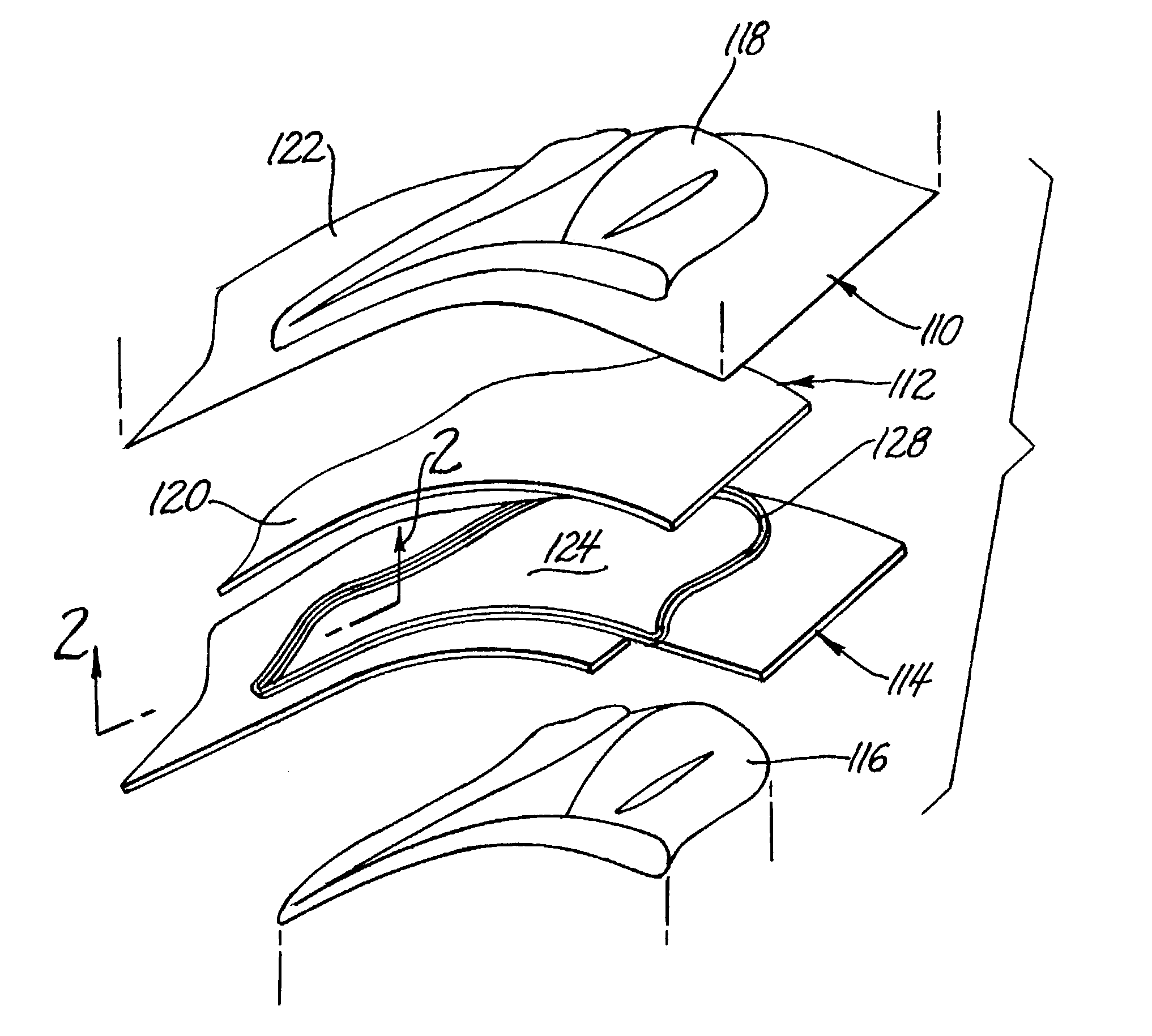
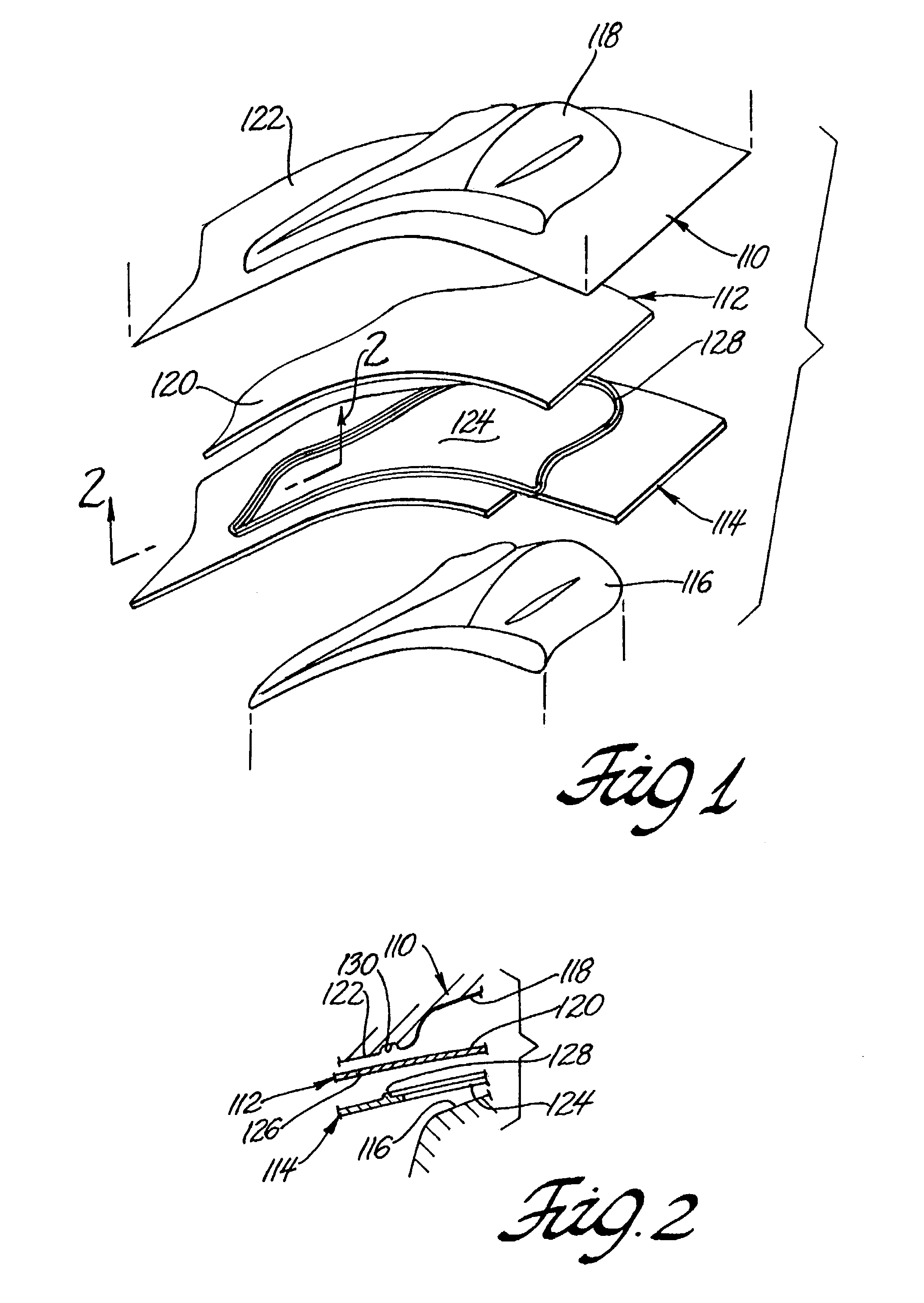
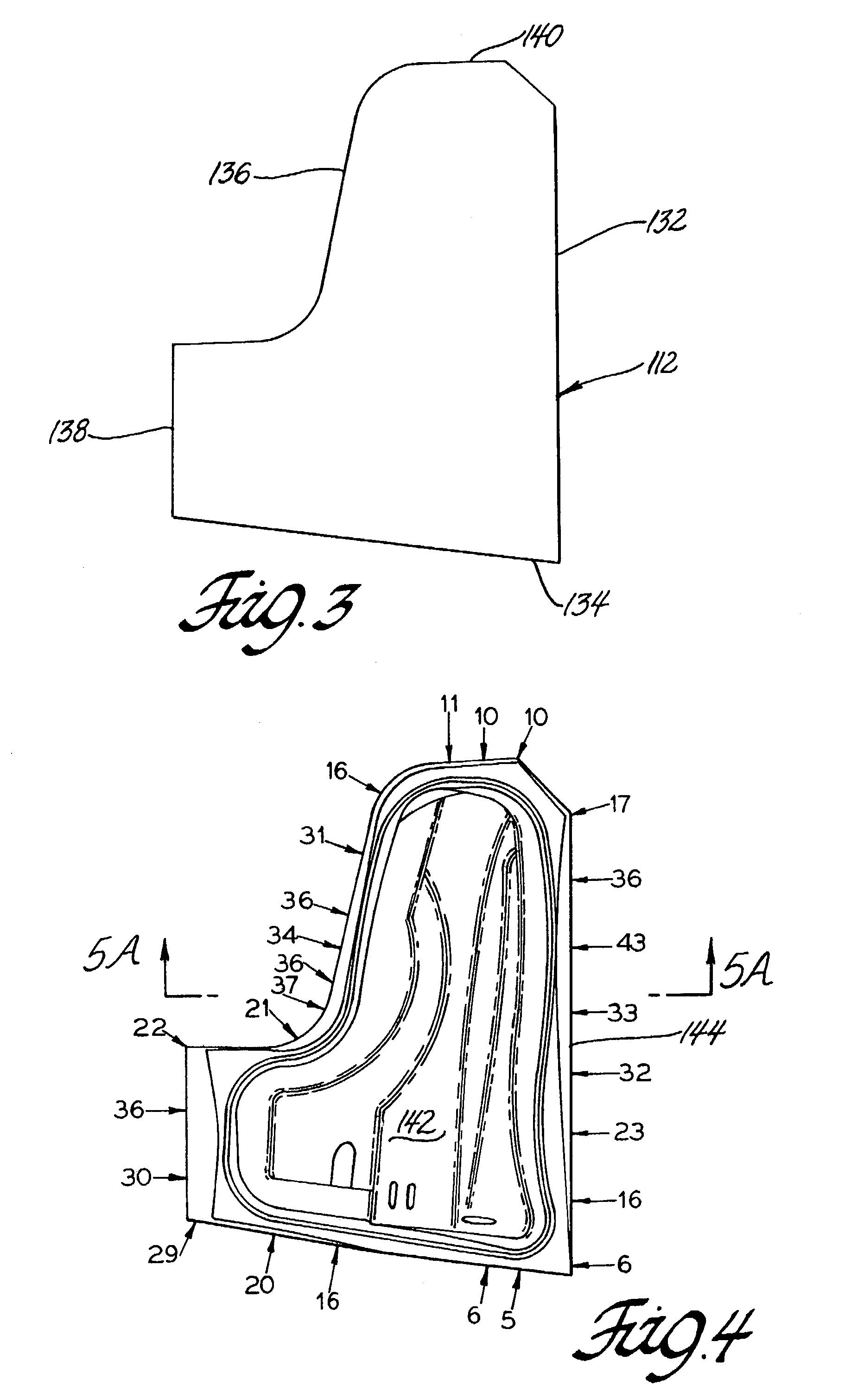
[0022]The practice of the invention is illustrated in connection with the stamping of an automotive vehicle fender outer panel. The fender panel may be stamped using a suitable low carbon steel metal blank or aluminum alloy blank, or the like. A shape for the fender is conceived by automotive designers. The design is transcribed into mathematically based dimensional and spatially locating data for use in computer assisted engineering design of a die set for the stamping of the fender panel. Commercially available computer based programs such as those identified above are used to then design a female die surface and a male punch surface and a binder ring shape suitable for controlling the stamping of the selected sheet metal material. Data concerning the thickness of the sheet metal, its physical properties and its deformation forming characteristics are used in the computer program in the design of the die set. Some panel shapes may require more than one stamping operation and, thus...


PUM


Abstract

Sheet metal forming is a manufacturing process in which flat sheet metal is drawn into a die cavity to form a product shape. Draw-in amount is the single most important stamping index that controls all forming characteristics (strains and stresses), formability failures (splits, wrinkles) and surface quality (distortions) on a panel. Adaptation of a new die set for repetitively stamping sheet metal parts to a part design specification is simplified by using a math-based simulation of the stamping operation under specified engineering stamping conditions for the specified part. The stamping simulations are used to create an engineered draw-in map comparing selected locations on the peripheral edge of the stamped part with corresponding locations on the peripheral edge of its original sheet metal blank. The resulting map of sheet metal draw-in dimensions reflect suitable displacements of the metal sheet between the binder ring and binder surface of the female die member at all such locations as the punch member of the die set executes its stamping operation. The engineered draw-in dimensions for a simulated part identify specific locations for adjustment of the binder ring / binder surface system in adapting the die set for production of parts.

Description

TECHNICAL FIELD[0001]This invention pertains to sheet metal formability and die making, and to methods for tryout of dies for sheet metal forming. More specifically, this invention relates to the use of a map of sheet metal draw-in or displacement distances around the periphery of a stamped sheet metal part in math-guided tryout of a three or four component die set comprising a punch, binder ring(s) and female die designed for making the part.BACKGROUND OF THE INVENTION[0002]A conventional three-component die set for stamping sheet metal parts consists of a punch, a binder ring and a female die. Such die sets are used to make many strong and light weight articles of manufacture. These articles include, for example, automotive body panels and other structure parts; aircraft and appliance sheet components; and beverage cans. Families of formable ferrous and aluminum sheet metal alloys have been developed for these manufacturing processes.[0003]In a typical sheet metal forming operatio...

Claims


Application Information

Patent Timeline
IPC IPC(8): G06F19/00B21D37/20G06G7/48
CPCB21D37/20
Inventor WANG, CHUAN-TAOGOAN, NORMANZHANG, JIMMY J.
Owner GM GLOBAL TECH OPERATIONS LLC
Learn More