
Flightless rock auger for use with pressure drills with quick attachment and method of use

Inactive Publication Date: 2006-11-07
GATOR ROCK BITS
View PDF22 Cites 16 Cited by
  • Summary
  • Abstract
  • Description
  • Claims
  • Application Information

AI Technical Summary

Benefits of technology

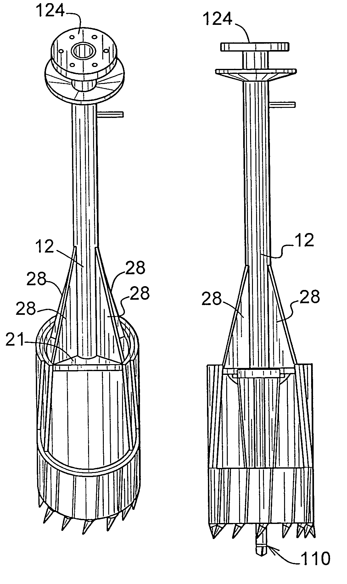
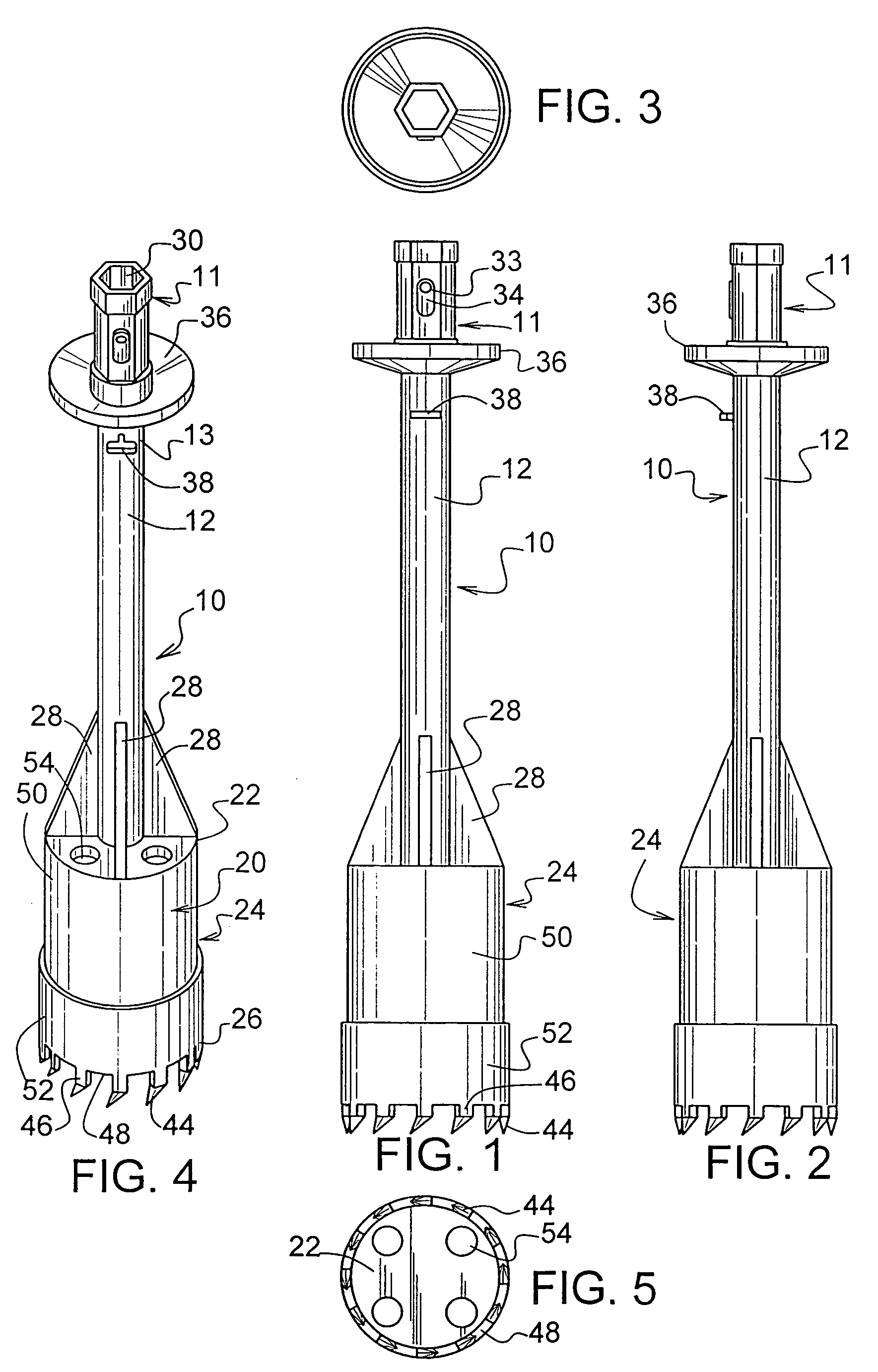
[0009]One preferred embodiment of the flightless rock auger system for use with a drilling rig includes a flightless rock auger having a cylindrical hollow cutting head with a plurality of cutting teeth extending from the bottom edge of the cutting head. A support member extends across a portion of the cylindrical hollow cutting head providing a means for cooperative engagement with a vertical drive shaft extending outwardly therefrom. A quick disconnect coupling is disposed upon the distal end of the shaft. A means for rotating the drive shaft such as a mechanical or fluid drive may also power the hydraulic mechanism for lifting and lowering the drive shaft which may utilize its own weight for exertion of downward pressure onto the hard substrate. Embodiments utilizing a coupling affixed directly to the top of the cutting head are well suited for use with pressure drilling rigs whereby force may be applied to the auger to provide quicker drilling.
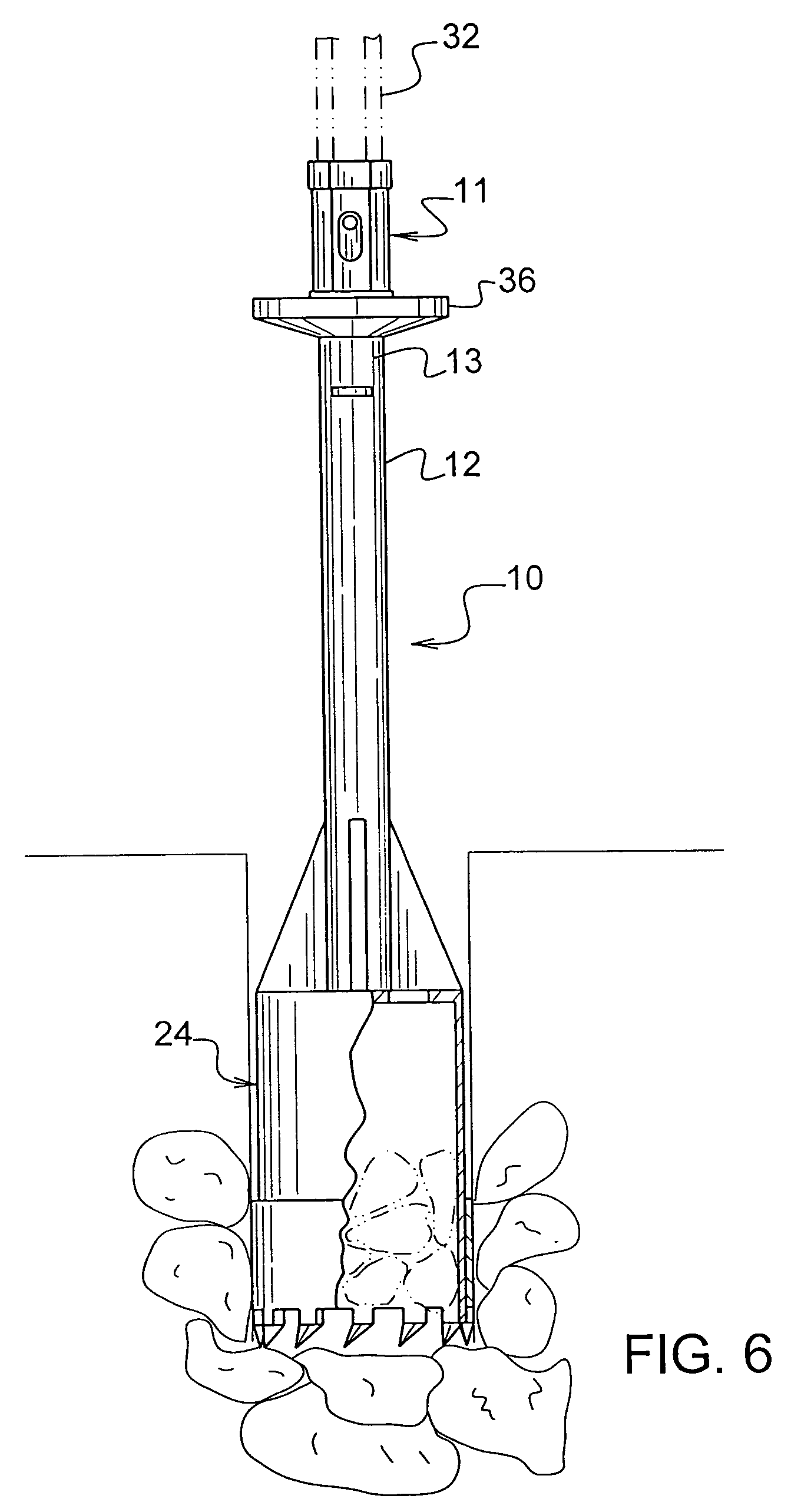
[0011]On the shaft models, a quick disconnect coupling is disposed upon the distal end of the shaft to means for rotating the drive shaft. On some pressure drilling flightless rock augers the shaft of the pressure drill rigs cooperatively engage a coupling mounted to the top of the auger body with a reinforced connections. The flightless rock auger is lowered into a posthole containing a hard substrate and resting the flightless rock auger onto the hard substrate. The auger is rotated at a very low rpm of up to 60 rpm, but more preferably up to 30 rpm and most preferably in a range of from between about 3 rpm to about 10 rpm forming a plug of hard substrate inside of the cylindrical body of the flightless rock auger. Lifting the flightless rock auger and the plug from the posthole is simple and the plug of the hard substrate is removed from the flightless rock auger head. The flighted auger is then substituted for removing soil from the posthole.
[0013]The rock auger is utilized in combination with a conventional flighted auger used for drilling postholes in dirt and clay. During a posthole drilling operation, the rock auger is substituted for the flighted auger when needed to drill through and remove rock or other hard material such as concrete from the posthole. The rock auger is designed for use at very low revolutions per minute and can utilize only the weight of the auger and shaft and does not require any additional hydraulic pressure for cutting a circular hole through the rock and forming a plug which is be lodged in the cavity of the rock auger cylinder to be removed from the posthole. Of course, most trucks or drilling rigs are equipped with hydraulic means for exerting pressure on the cutting head to increase the cutting rate and is often utilized with the shaft and cutting head and usually utilized with the pressure drilling head having a quick disconnect near the top of the cutting head body. The quick connection shaft enables the conventional flighted auger to be quickly substituted for the flightless rock auger to facilitate fast removal of soft dirt from the posthole. The rock auger provides a means for utility companies to utilize a means for drilling postholes for electric poles, telephone poles, pilings, and the like without the use of explosives; thereby providing a safer means of excavation.
[0017]Of course, the power drive shaft of the auger drive unit can also be connected to the shaft of the auger by a coupling which limits or even eliminates any play and provide a tight cooperative engagement therebetween. The auger and cutting head will still float in that only the weight of the auger will be necessary to cut through the rock substrate. If desired the cutting may be faster by also letting the power drive boom weight rest on the auger thereby floating on the rock substrate during the drilling process. Of course, applying downward pressure to the auger by use of the boom is an option to increase the cutting rate; however, unnecessary to obtain good performance. Thus, the pressure drill model provides rapid cutting motion through the substrate.
[0022]It is therefore another object of the present invention to design a flightless auger for use at very low revolutions per minute (rpm) to maximize safely and prevent damage to the equipment.

Problems solved by technology

Although the conventional flighted auger is adequate for drilling through soil, or even soil with loose rock, the drilling operation must be suspended upon hitting a large rock or rock ledge because the flighted auger cannot penetrate the hard rock surface.
A considerable amount of time is lost during the rock break-up and removal procedure.
Moreover, an effort is continually being made to minimize work with explosives due to the liability of injury to workers and / or damage to residents or businesses in the area which may be in the area of the blasting zone and susceptible to rock or vibration damage.

Method used


Image

  • Flightless rock auger for use with pressure drills with quick attachment and method of use
  • Flightless rock auger for use with pressure drills with quick attachment and method of use
  • Flightless rock auger for use with pressure drills with quick attachment and method of use

Examples


Embodiment Construction

[0064]The flightless rock auger 10 with quick attachment coupling 11 of the present invention is manufactured from readily available materials and simple in design. The preferred embodiment is comprised of metal, more particularly steel. The rock auger 10 is mounted on construction equipment such as hydraulic drilling rigs. A drive shaft 12 in communication with a drilling rig motor 14 or circulation of a hydraulic fluid from a pump on the drilling rig 16 may be used to drive the hydraulic motor 18 of the construction equipment.

[0065]Referring now to the drawings, FIGS. 1–8 refer to the present invention including a standard drive shaft 12 utilizing a quick disconnect coupling 11 extending from the distal end 13 of the shaft 12. The shaft 12 is centrally aligned with the axis of the hollow cylindrical body 20 and secured to the proximal end, or top end of the cutting head 24 opposite the open end 26 having the cutting or a sraping edge. The top end is at least partially enclosed by ...


PUM

PropertyMeasurementUnit
Lengthaaaaaaaaaa
Diameteraaaaaaaaaa

Abstract

A flightless rock auger is used for drilling postholes through rock with the use of hydraulic pressure and at slow revolution per minute. The rock auger is used in combination with a conventional flighted auger used for drilling postholes in dirt and clay. During a posthole drilling operation, the rock auger is substituted for a conventional flighted auger as needed for drilling through and removing rock or other hard material such as concrete from the posthole. The rock auger is designed for use at very low revolutions per minute and can function utilizing only the weight of the auger; however, the rock auger is designed for use with pressure drilling units as well for cutting a circular hole through the rock and forming a plug which is to be lodged in the cavity of the rock auger cylinder to be removed from the posthole. The quick connection enables the shaft of a pressure drill unit to engage the flightless auger to be quickly substituted for the rock auger to facilitate fast removal of soft dirt from the posthole. A pilot drill bit can be disposed within the cutting head for extending outwardly pass the cutting edge thereof for starting the hole, breaking up rock, and holding the auger in position during the drilling operation. A portion of the cylindrical body can be removed to allow quick clearance of the plug.

Description

[0001]This is a Continuation-In-Part of U.S. application Ser. No. 10 / 032,216 filed on Dec. 20, 2001 now U.S. Pat. No. 6,619,413 , which is a Continuation-in-Part of Ser. No. 09 / 684,821 file on Oct. 10, 2000 now U.S. Pat. No. 6,494,276 which is a Continuation-In-Part of Ser. No. 09 / 066,194 filed on Apr. 24, 1998, now U.S. Pat. No. 6,129,163 and claims priority from U.S. Provisional Applications Ser. No. 60 / 203,061 filed on May 9, 2000 and Ser. No. 60 / 185,664 filed on Feb. 29, 2000.BACKGROUND OF THE INVENTION[0002]The present invention relates to a flightless rock auger suspended from a derrick and powered by a shaft linked to a power source for removing plugs of rocks from post holes.[0003]Poles for power lines and communication purposes are required to be vertical and arrange din straight lines. The poles may be planted in positions which are relatively inaccessible. A crane may be utilized for providing an outreaching means. Typically a digger derrick consists of a telescopic mobil...

Claims


Application Information

Patent Timeline
IPC IPC(8): E21B10/00E21B17/14E21B10/02
CPCE21B10/02Y10T408/94Y10T408/895
Inventor HAMILTON, GARY WAYNEHAMILTON, CHARLES
Owner GATOR ROCK BITS
Learn More