

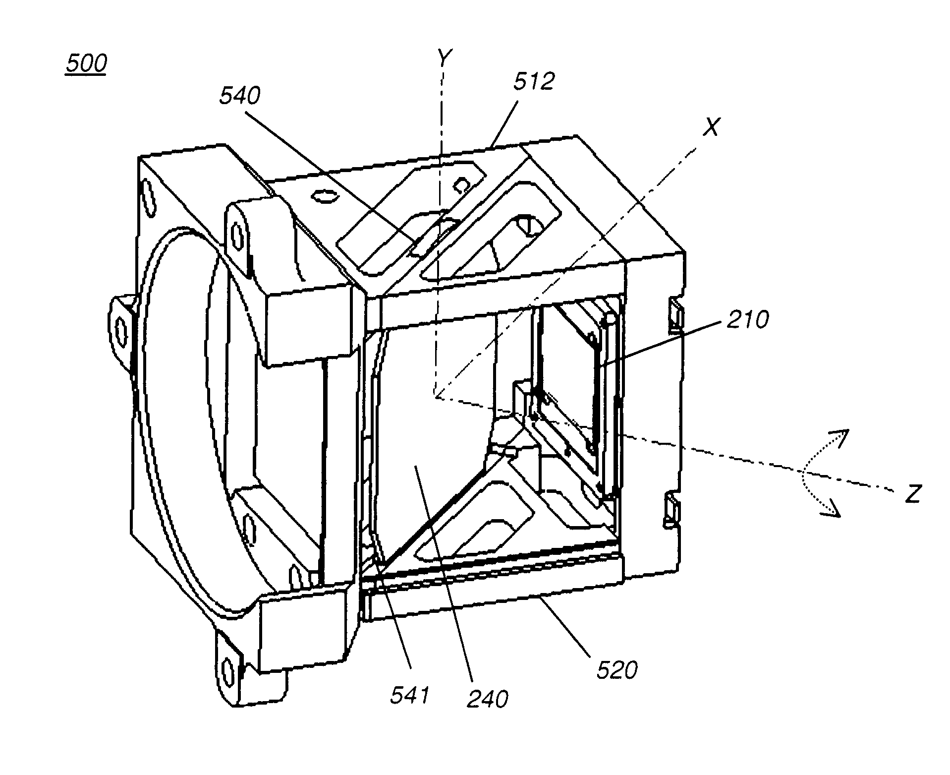
Housing for mounting a beamsplitter and a spatial light modulator with an output optical path
a beamsplitter and spatial light modulator technology, applied in the field of digital projection apparatus, can solve the problems of reducing the angular response of the beamsplitter, and other limitations, and achieve the effect of mechanical robustness and without degrading image quality
- Summary
- Abstract
- Description
- Claims
- Application Information
AI Technical Summary
Benefits of technology
Problems solved by technology
Method used
Image

Examples
Embodiment Construction
[0045]The present description is directed in particular to elements forming part of, or cooperating more directly with, apparatus in accordance with the invention. It is to be understood that elements not specifically shown or described may take various forms well known to those skilled in the art.
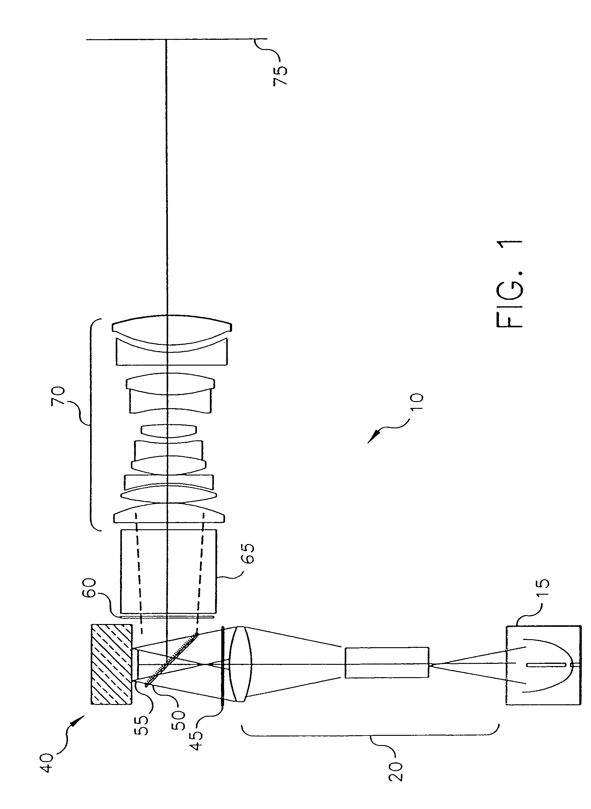
[0046]Referring to FIG. 1, there is shown in schematic form the arrangement of optical components in a digital projection apparatus 10, as described in commonly-assigned U.S. Pat. No. 6,585,378 (Kurtz et al.) Illumination optics 20 and pre-polarizer 45 precondition light from a light source 15 to provide illumination that is essentially uniformized and polarized. Illumination optics 20 includes uniformizing optics, such as an integrating bar or a fly's eye integrator assembly, and condensing relay optics assembly. This light is subsequently polarized by pre-polarizer 45, with light of the desired polarization state directed towards the polarization beamsplitter, while the rejected alternat...
PUM
| Property | Measurement | Unit |
|---|---|---|
| azimuthal angles | aaaaa | aaaaa |
| azimuthal angles | aaaaa | aaaaa |
| azimuthal angles | aaaaa | aaaaa |
Abstract
Description
Claims
Application Information