Method and system for designing ring-based telecommunications networks

a technology of telecommunications networks and ring-based communications, applied in data switching networks, time-division multiplexing selection, multiplex communication, etc., can solve the problems of limited equipment and features, limited the choice and options of network users and designers, and limited the equipment of network designers, so as to facilitate the formation and selection of one or more rings, the effect of processing traffic data files

Active Publication Date: 2006-11-07
TELLABS OPERATIONS
View PDF38 Cites 10 Cited by
  • Summary
  • Abstract
  • Description
  • Claims
  • Application Information

AI Technical Summary

Benefits of technology

[0024]In one aspect, a further set of executable instructions facilitates the formation and selection of one or more rings for forming the bi-connected representation of the network. A still further set facilitates the processing of the traffic data file for routing the traffic through the bi-connected representation of the network.

Problems solved by technology

One of the challenges facing telecommunication providers is that existing networks are continuously needing to be updated, in order to keep up with ever increasing customer demands and anticipated future demand including the demand for increased data transmission speeds and capacity.
One of the earlier hurdles to designing networks incorporating early generations of fiber-optic systems, integrated as part of the public telephone network, involved the extensive use of proprietary architectures by equipment manufacturers including corresponding proprietary hardware and communication protocols.
The proprietary architectures limited the ability of network users and designers, like Bell operating companies and inter-exchange carriers to integrate equipment from different suppliers into their systems, when developing or updating a network.
This significantly limited the designers choices and options in terms of equipment and features after an initial proprietary scheme was selected to the available features incorporated into the equipment compatible with the proprietary scheme.
In many cases this limited the network designer to equipment produced or supplied by a single vendor.
However as the number of locations and the corresponding amount of network traffic traveling between locations increases, decisions as to how to define the rings and how to deploy the communication equipment in an efficient and a cost effective manner can become quite complex.

Method used


Image

  • Method and system for designing ring-based telecommunications networks
  • Method and system for designing ring-based telecommunications networks
  • Method and system for designing ring-based telecommunications networks

Examples


Embodiment Construction

[0040]While this invention is susceptible of embodiment in many different forms, there are shown in the drawing and will be described herein in detail specific embodiments thereof with the understanding that the present disclosure is to be considered as an exemplification of the principles of the invention and is not intended to limit the invention to the specific embodiments illustrated.

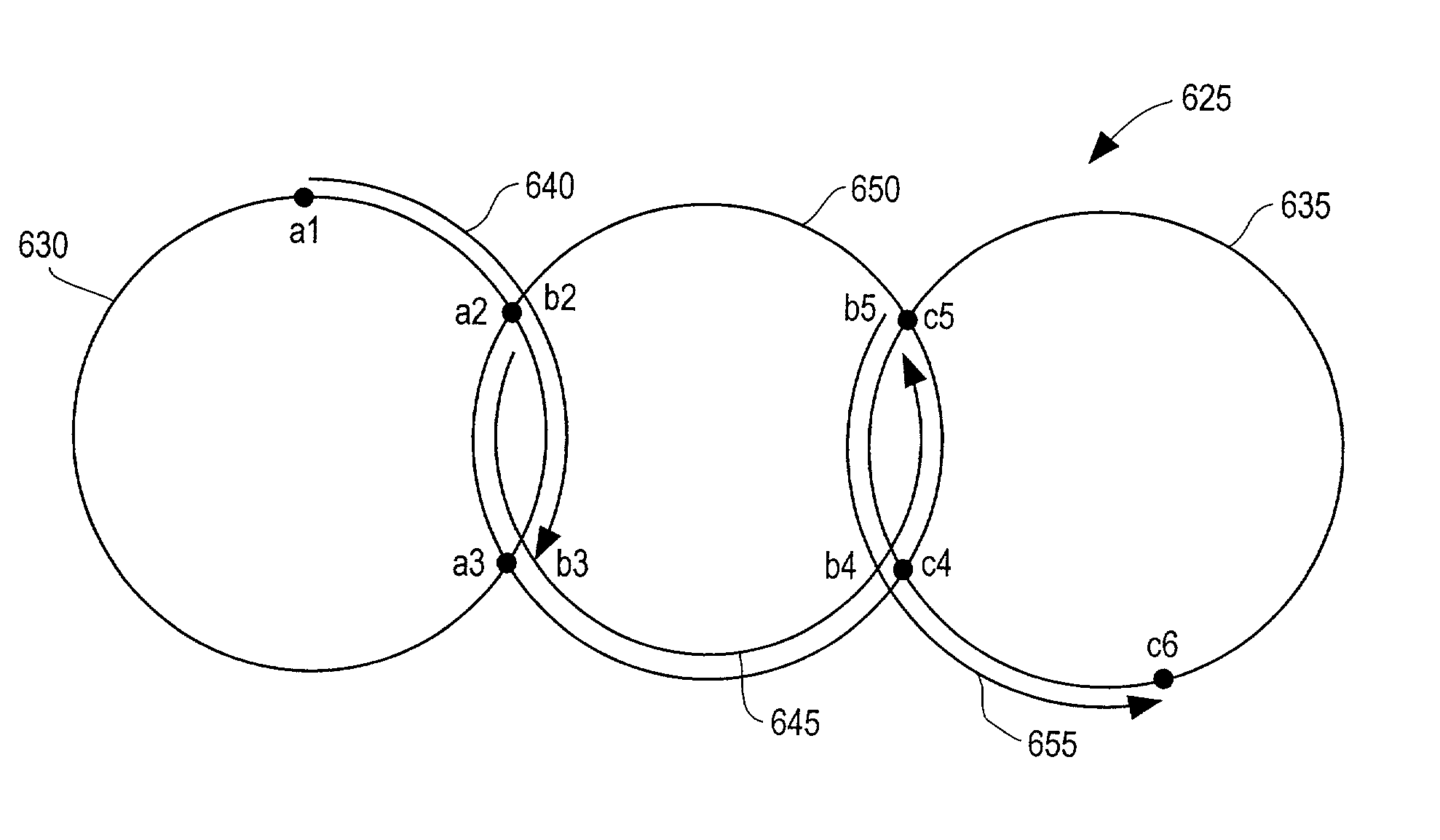
[0041]Generally Sonet-based ring networks include multiple locations coupled together in sequence in a ring configuration, where the first location of the sequence is directly connected to the last location in the sequence. Typically associated with each location, are add-drop multiplexers which can facilitate the insertion or removal of signal traffic from the ring. The traffic can be either uni-directional or bi-directional.

[0042]As noted previously, one of the features of a ring topology is its survivability. If one of the connections is cut, the add-drop multiplexers are programmed to reroute th...


PUM


Abstract

A method and system for designing a bi-connected ring-based network is provided, which designs from scratch or converts an existing network to a dual-homed ring-based network. The network covers the locations capable of being bi-connected with one or more cycles/rings. The traffic demand is then routed via the cycles, in such a way so as to minimize the amount of network traffic management equipment required.

Description

[0001]This application claims the benefit of U.S. Provisional Application Ser. No. 60 / 268,201, filed Feb. 12, 2001, and U.S. Provisional Application Ser. No. 60 / 270,094, filed Feb. 20, 2001.FIELD OF THE INVENTION [0002]The invention pertains to methods and systems for designing ring-based communications systems. More particularly, the methods and systems pertain to designing networks with dual-homed rings from previously non-ring based networks, from scratch, or to optimize already existing dual-homed or non-dual-homed ring-based networks.BACKGROUND OF THE INVENTION [0003]One of the challenges facing telecommunication providers is that existing networks are continuously needing to be updated, in order to keep up with ever increasing customer demands and anticipated future demand including the demand for increased data transmission speeds and capacity. One area of technology that has been increasingly used to keep up with customer demand is the use of optical signal transmission equi...

Claims


Application Information

Patent Timeline
Patent Type & Authority Patents(United States)
IPC IPC(8): H04L12/50H04J14/02H04Q11/04
CPCH04J14/0227H04J14/0283H04J14/0286H04J14/0295H04L12/28H04L12/42H04J14/0241H04J14/0284H04J2203/0042H04J2203/0055
Inventor CHOW, TIMOTHY Y.LIN, PHILIP J.MILLS, JAMES D.
Owner TELLABS OPERATIONS
Why Eureka
Try Eureka