Method and apparatus for processing digitally sampled signals at a resolution finer than that of a sampling clock

a sampling clock and digital signal technology, applied in pulse technique, navigation instruments, instruments, etc., can solve the problems of inability to perfectly synchronize, receiver clocks in general not as accurate as satellite clocks, and inherent time error in distance measurements, so as to facilitate synchronization with received signals and mitigate multipath effects

Inactive Publication Date: 2006-11-07
LEICA GEOSYSTEMS INC
View PDF4 Cites 16 Cited by
  • Summary
  • Abstract
  • Description
  • Claims
  • Application Information

AI Technical Summary

Benefits of technology

[0011]The method of the invention may also be defined as a method for reproducing a desired signal in synchronism with a signal event in a received signal, the method comprising the steps of generating sample clock signals spaced at sample intervals; generating sub-sample clock signals; deriving from the sub-sample clock signals a measure of clock phase within each sample interval; and generating the desired signal synchronized with a received signal event to an accuracy limited only by the sub-sample clock signals. The sample clock signals occur at a sampling clock rate that is nominally an integral multiple of the rate at which signal events may occur in the received periodic signal, but which cannot be exactly synchronized with the received periodic signal because of a frequency difference between the received signals and locally generated signals. Use of the sub-sample clock signals allow generation of the desired signal to a higher level of temporal accuracy. The step of generating the desired signal may also include generating a succession of signal magnitudes at times determined by the sub-sample clock signals, to provide a desired signal profile.
[0014]In a disclosed embodiment of the invention, the step of applying the frequency difference to the locally generated GPS code includes dividing the frequency difference by a selected value, using a counter to provide an output signal whenever the counter overflows, to indicate that the frequency difference has resulted in a cumulative phase error equivalent to a whole code rate period; and the step of deriving a code phase value includes multiplying the code rate period by the ratio of the current counter contents to a full counter value. The step of using the code phase value to generate a weighted signal window also preferably includes generating a succession of signal values of selected magnitudes, at times precisely determined from the code phase values, wherein the signal window is synchronized with a received signal event and has a desired profile. The desired window profile may be selected for any purpose, such as to mitigate multipath effects in the receiver, or for optimal detection of a signal pulse after the received signals have passed through a communication channel of limited bandwidth.
[0018]More specifically, the counter circuit for deriving a code phase value divides the frequency difference by a selected value and provides an output signal whenever the counter overflows, to indicate that the frequency difference has resulted in a cumulative phase error equivalent to a whole code rate period, wherein this output signal is coupled to the adjustable divider circuit; and the apparatus further comprises a code phase generation circuit, for multiplying the code rate period by the ratio of the current counter contents to a full counter value. The signal window generator may include means for generating a succession of signal values of selected magnitudes, at times precisely determined from the code phase values, wherein the signal window is easily synchronized with a received signal event and has a desired profile. The signal window generator provides a desired window profile selected to achieve a desired goal, such as to mitigate multipath effects, or for optimal detection of a signal pulse after the received signals have passed through a communication channel of limited bandwidth.

Problems solved by technology

Because a receiver clock cannot be exactly synchronized with clocks on the satellites, there is, however, an inherent time error in the distance measurements, which are referred to as pseudoranges.
Although, both the satellite and the receiver may use digital clocks that are nominally synchronous in terms of frequency, they will not be perfectly synchronous, for two reasons.
First, the receiver clock will in general not be as accurate as the satellite clock and there will inevitably be a slight frequency difference between the two clocks.
Because of this unavoidable asynchronous relationship between sample clocks on a satellite and on the receiver, the event under consideration cannot be faithfully reproduced in the receiver.
A similar problem arises if one wishes to reproduce a non-digital event, such as a periodic analog signal, using a signal generator that is limited by the use of a digital sampling technique.
There is, however, an inherent difficulty in sampling across a desired window if the starting and ending points of the window do not coincide with available digital sample points.
The multipath mitigation windows described in the patents referenced above are limited in shape.
Although a digital signal event may be close to this ideal when transmitted, the same signal event as received will be necessarily distorted in profile because any practical transmission channel is limited in bandwidth and cannot, therefore, faithfully transmit instantaneous changes in signal level.

Method used


Image

  • Method and apparatus for processing digitally sampled signals at a resolution finer than that of a sampling clock
  • Method and apparatus for processing digitally sampled signals at a resolution finer than that of a sampling clock
  • Method and apparatus for processing digitally sampled signals at a resolution finer than that of a sampling clock

Examples


Embodiment Construction

[0037]As shown in the drawings for purposes of illustration, the present invention pertains to a method and apparatus for reproducing a desired periodic signal event, such as a signal waveform or a desired signal time window, without being limited in temporal resolution by a digital sampling interval and without being limited to a small number of specific signal magnitudes. As briefly described above, the accuracy of reproduction of signal events and sampling windows is limited by the use of a digital sampling interval. This limitation will now be described further with reference to the drawings.

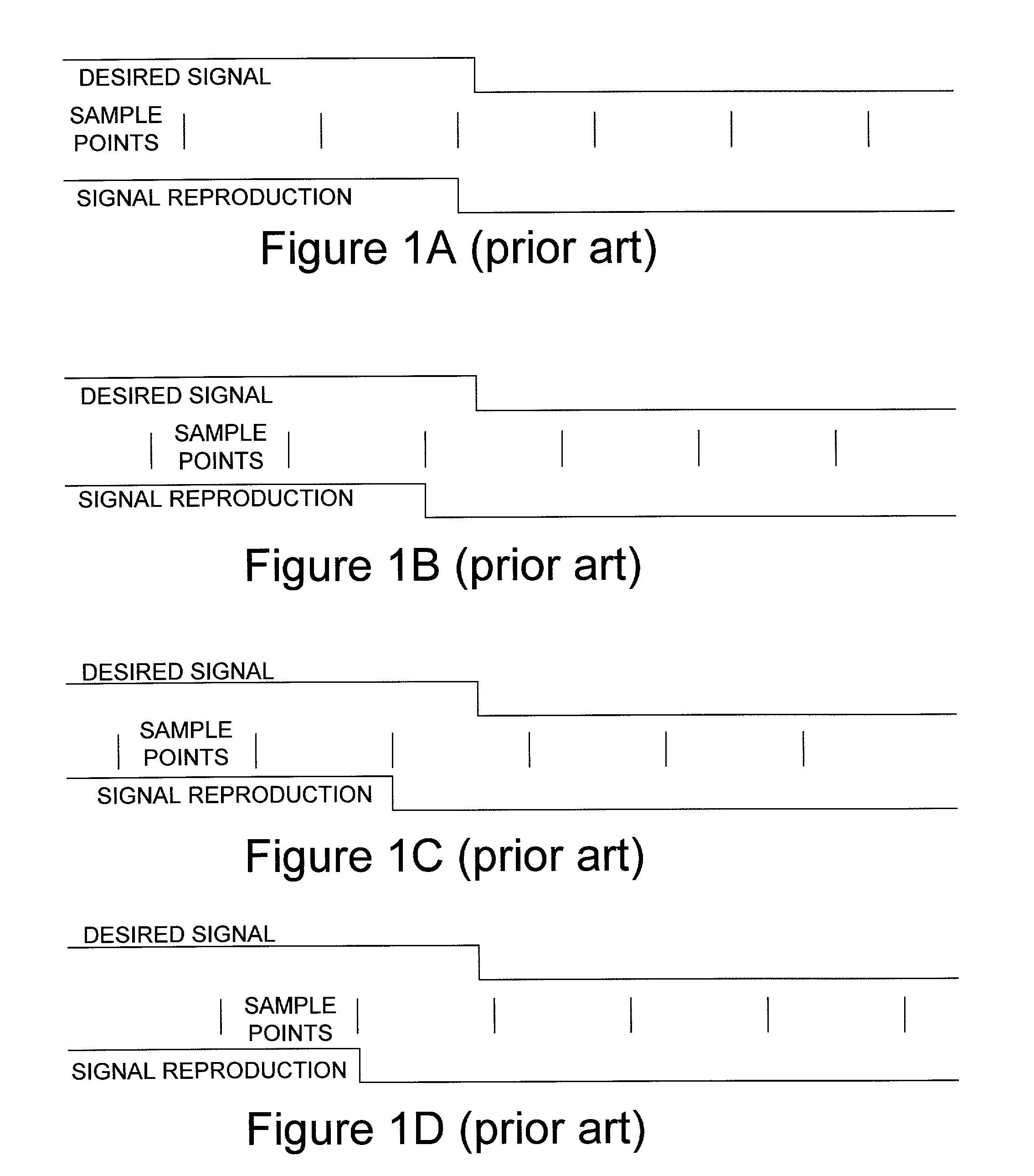
[0038]FIGS. 1A–1D depict how a periodic digital event may be represented or reproduced using digital sampling. In each of the figures, the upper waveform is the desired signal event to reproduce and the lower waveform is the reproduced signal. The event in this case is a digital transition from a high level to a lower level. In between the upper and lower waveforms, short vertical lines repr...


PUM


Abstract

A method and related apparatus for reproducing a periodic signal received over a communication channel, or signal window of a desired profile, wherein the resolution of the reproduced signal or window is not limited by a digital sampling interval. The profile can be selected to match and compensate for known or estimated characteristics of a communication channel. A frequency difference, due to a Doppler frequency shift or other errors between received signals and locally generated signals, is determined in a receiver and utilized to derive a fine code phase measurement that is then usable to generate a succession of magnitudes that reproduce the desired signal or window profile.

Description

BACKGROUND OF THE INVENTION[0001]This invention relates generally to techniques for reproducing a signal or event by using discrete digital samples and, more particularly, to techniques for reproducing periodic signals or events in the processing of global positioning system (GPS) signals. Although the present invention has application in areas other than GPS signal processing, the GPS environment provides a useful context for describing the invention and its background.[0002]As is well known, a GPS receiver can accurately determine its position in three dimensional space, based on radio-frequency (RF) signals received simultaneously from multiple earth-orbiting satellites. There is a sufficient number of satellites in orbit to allow more than one (and preferably at least four) to be visible to a receiver at any point on or above the earth. The signals transmitted from each satellite uniquely identify the satellite and also include ephemeris data that define the satellite orbit. Fro...

Claims


Application Information

Patent Timeline
Patent Type & Authority Patents(United States)
IPC IPC(8): H04L7/00G01S19/09G01S1/00G01S5/02G01S19/14G01S19/35H04L7/033H04L27/00
CPCG01S5/0215G01S19/22G01S19/29G01S19/30H04L7/0334G01S19/37H04L2027/0028H04L2027/0057
Inventor COLBORNE, STEVEN FRANCISKEEGAN, RICHARD GERALD
Owner LEICA GEOSYSTEMS INC
Why Eureka
Try Eureka