
Disc cutter

a technology of disc cutter and disc cutter, which is applied in the direction of manufacturing tools, couplings, mechanical equipment, etc., can solve the problems of difficult cleaning, unreliable cutting action, and relatively unstable utensils

Active Publication Date: 2006-11-14
FEY INDS
View PDF20 Cites 21 Cited by
  • Summary
  • Abstract
  • Description
  • Claims
  • Application Information

AI Technical Summary

Problems solved by technology

These prior cutting utensils are known to have relatively unstable and unreliable cutting action and can be difficult to properly clean.

Method used


Image

  • Disc cutter
  • Disc cutter
  • Disc cutter

Examples


Embodiment Construction

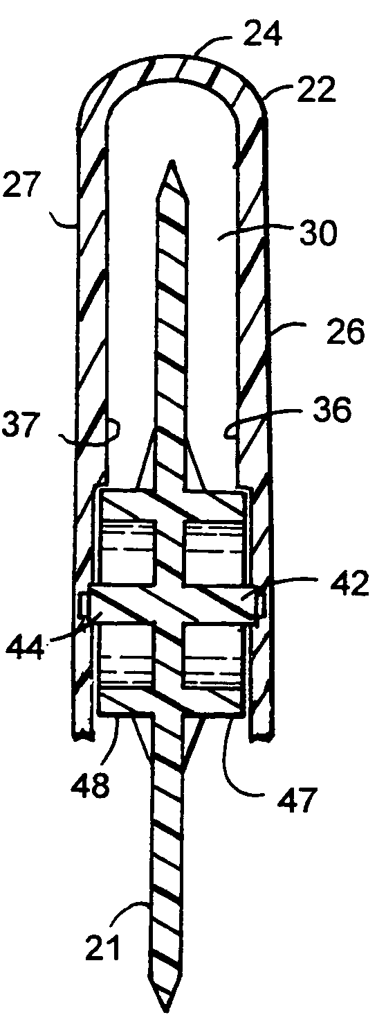
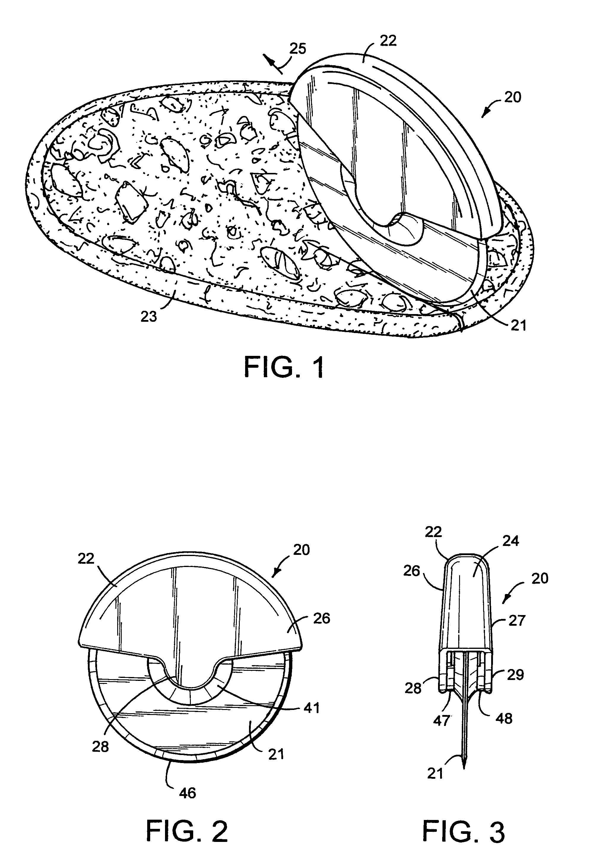
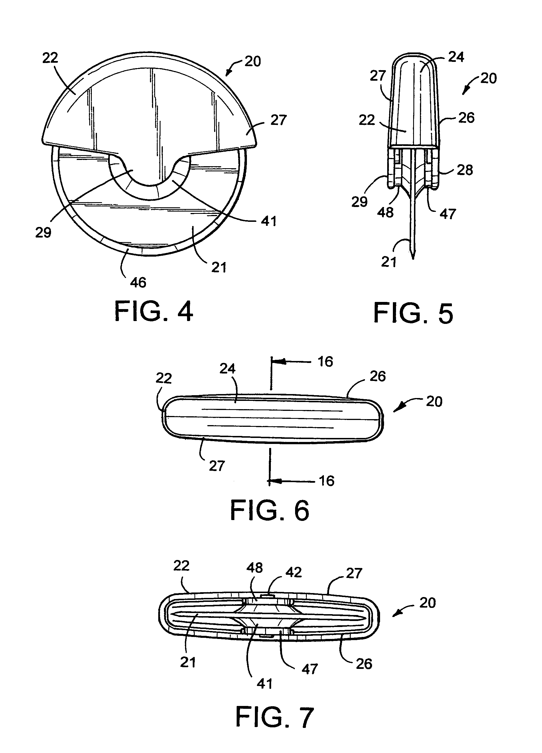
[0021]Referring to FIGS. 1 to 7, there is shown a disc cutter assembly, indicated generally at 20, useable as a food processing and cutting utensil for slicing pizza 23 or chopping and cutting flat breads, pastries, raisins, apples, spices, herbs and the like. Cutter 20 has a handle 22 and a removable disc cutter or cutting wheel 21 releasably mounted on handle 22. Cutting wheel 21 is a generally flat one-piece circular plastic member having a relatively sharp annular cutting edge 46. Cutting wheel 21 can be made from other materials such as metal, and have other types of cutting edges such as a fluted cutting edge (not shown) for cutting pastries.

[0022]Handle 22 is a hollow molded plastic semi-circular shaped housing member having semi-rigid semi-circular shaped side walls 26 and 27 joined to an arcuate concave curved semi-circular top wall 24. Side walls 26 and 27 can be expanded and slightly flexed outwardly and moved apart to allow cutting wheel 21 to be moved into and out of a ...


PUM

PropertyMeasurementUnit
flexibleaaaaaaaaaa
shapeaaaaaaaaaa
resiliently flexibleaaaaaaaaaa

Abstract

A pizza cutter has a hollow semi-circular shaped handle having a convex curved radiused top edge to facilitate use and reduce hand stress. A removable cutter wheel has outwardly extending axles having protrusions on the outer ends thereof that have a snap fit relationship with recesses on the inner surfaces of the handle whereby the cutter wheel can easily be snapped into and out of the handle for cleaning. The cutter wheel has a dual inner and outer axle assembly engaging complementary shaped bearing surfaces on the handle to distribute pressure exerted on the wheel and keep the cutter wheel aligned with the handle when cutting movement is applied to the cutter.

Description

FIELD OF THE INVENTION[0001]The invention is directed to a disc cutting kitchen utensil for cutting and processing food such as pizza, and the like, particularly ergonomic cutters with quick release blades.BACKGROUND OF THE INVENTION[0002]Pizza cutter tools with cutting wheels commonly have an elongated stick-shaped handle with a non-removable wheel. These prior cutting utensils are known to have relatively unstable and unreliable cutting action and can be difficult to properly clean.SUMMARY OF THE INVENTION[0003]The invention comprises a food processing cutting utensil having a housing with resiliently flexible side walls joined to a semi-circular shaped top wall. A cutter disc is releasably mounted in the housing. The disc has outwardly directed axles which are joined to the center of the disc. The axles are rotatably located in grooves on the housing to rotatably mount the disc on the housing. The disc extends through a slot in the bottom of the housing to expose a cutting edge u...

Claims


Application Information

Patent Timeline
Patent Type & Authority Patents(United States)
IPC IPC(8): B26D1/143B26D1/14B26B29/00
CPCB26D7/2621B26B25/005Y10T403/32344Y10T83/9466
Inventor MOLENAAR, STEVEN L.
Owner FEY INDS
Learn More