

Non-penetrating filtration surgery
- Summary
- Abstract
- Description
- Claims
- Application Information
AI Technical Summary
Benefits of technology
Problems solved by technology
Method used
Image

Examples
Embodiment Construction
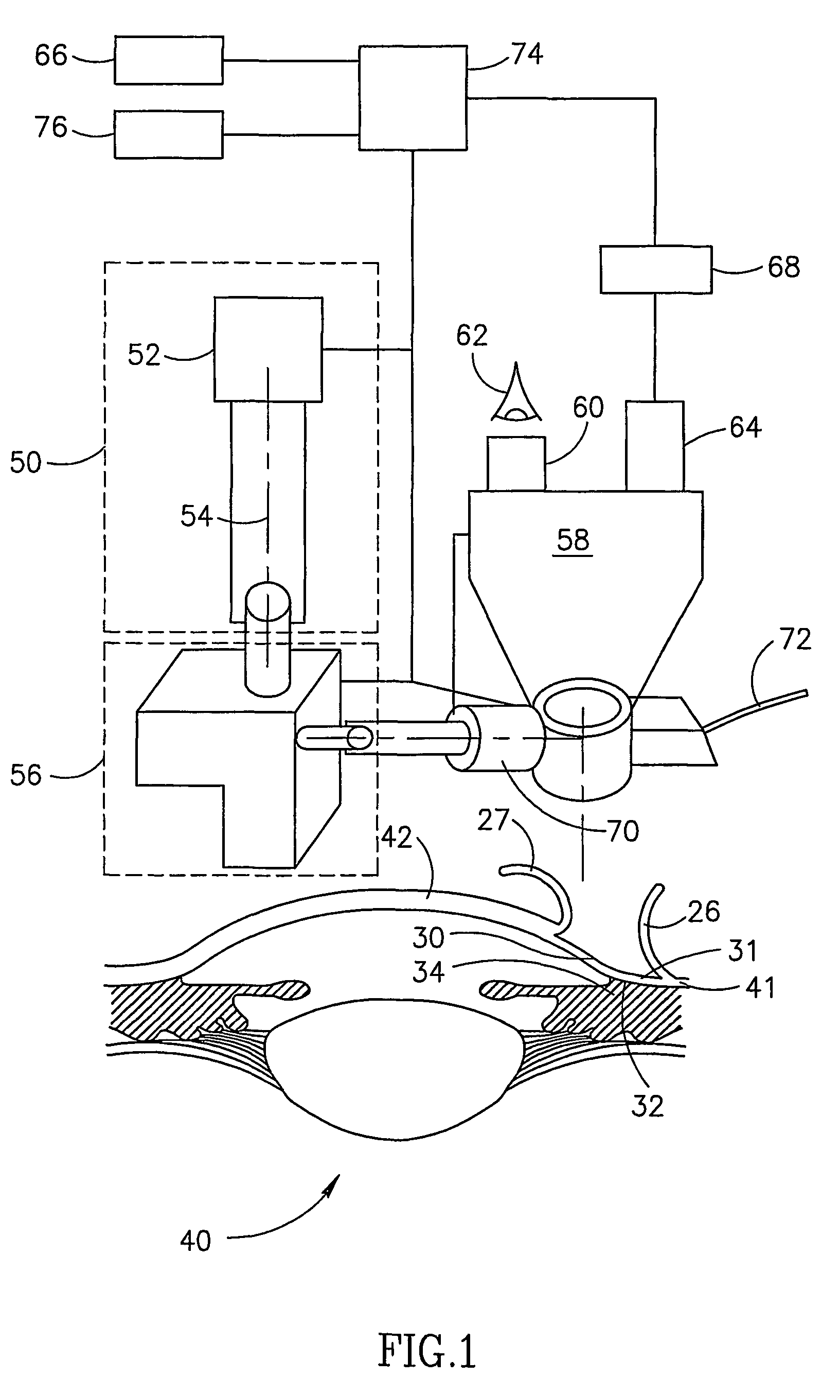
[0048]FIG. 1 is a schematic illustration of an exemplary ophthalmologic ablation system 50, during a non-penetrating filtration procedure in accordance with an exemplary embodiment of the invention.
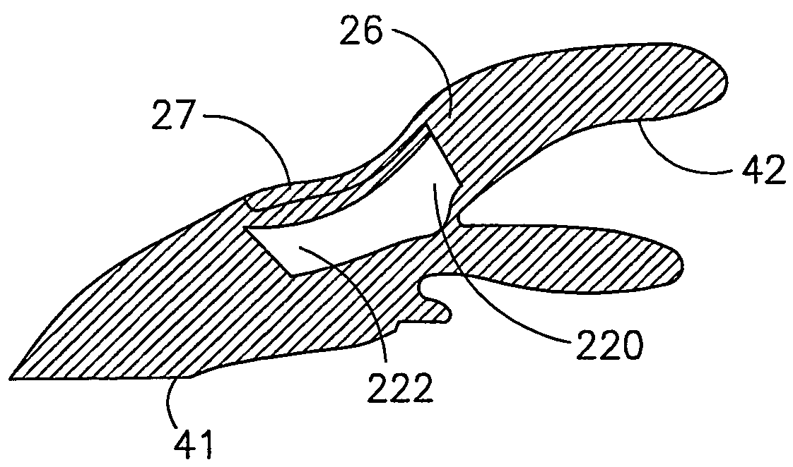
[0049]Referring first to an eye 40, an exemplary filtration procedure using system 50 comprises ablating parts of an area 31 of a sclera 41 and / or a cornea 42 in an area 30. Some of the ablation is directed to those areas overlying a Schlemm's canal 34 and / or trabecular meshwork 32. The size of area 30 is exaggerated in FIG. 1, as in many procedures, area 30 is significantly smaller than area 31 and may comprise substantially only the boundary area between cornea 42 and sclera 41 that overlies the Schlemm's canal. In some procedures, however, a larger portion of the cornea may be ablated. A more detailed description of an exemplary filtration procedure is provided below.
[0050]System 50 comprises a laser source 52 that generates an ablation laser beam 54. In one embodiment of the invention...
PUM
 Abstract
Description
Claims
Application Information