
Method and apparatus for controlling brushless DC motors in implantable medical devices

a brushless dc motor and implantable medical device technology, applied in the direction of electric controllers, dynamo-electric converter control, instruments, etc., can solve the problems of false triggering, unsuitable center tap in medical implant applications, and transportation needs to be provided

Inactive Publication Date: 2006-11-21
HEARTWARE INC
View PDF31 Cites 130 Cited by
  • Summary
  • Abstract
  • Description
  • Claims
  • Application Information

AI Technical Summary

Benefits of technology

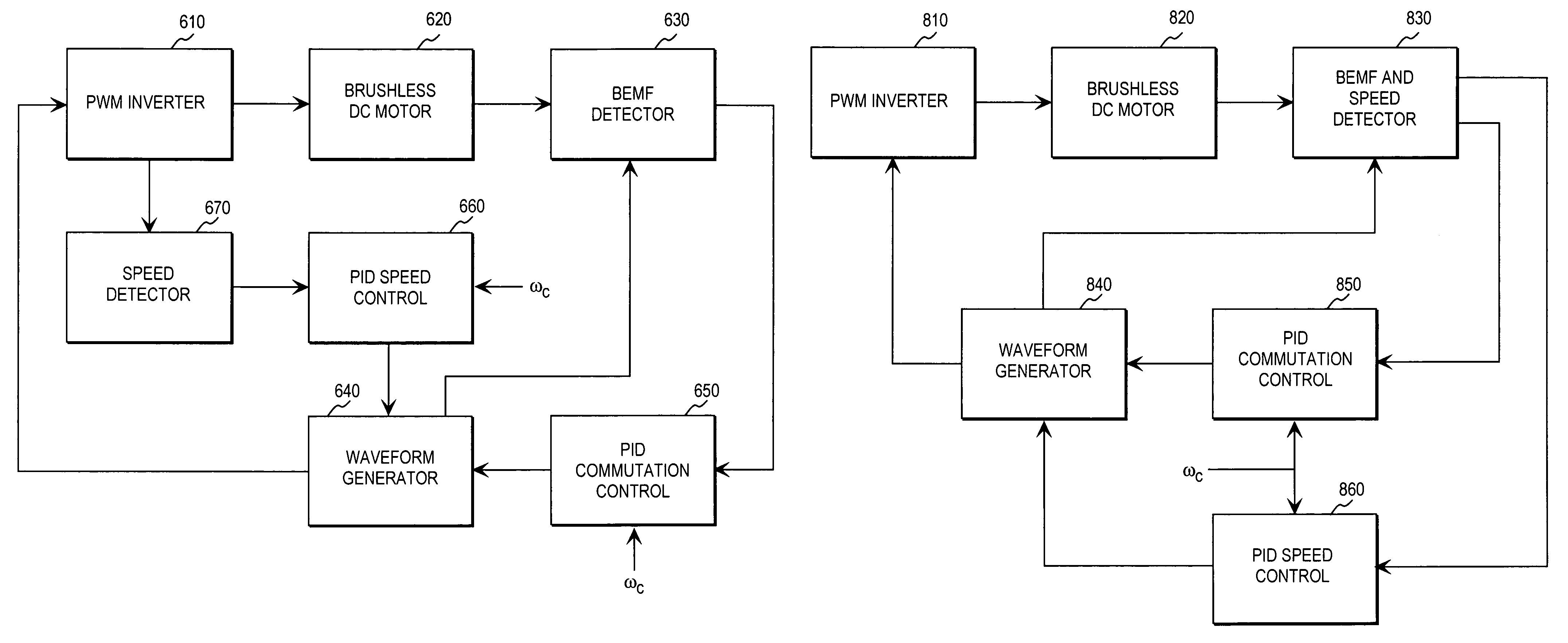
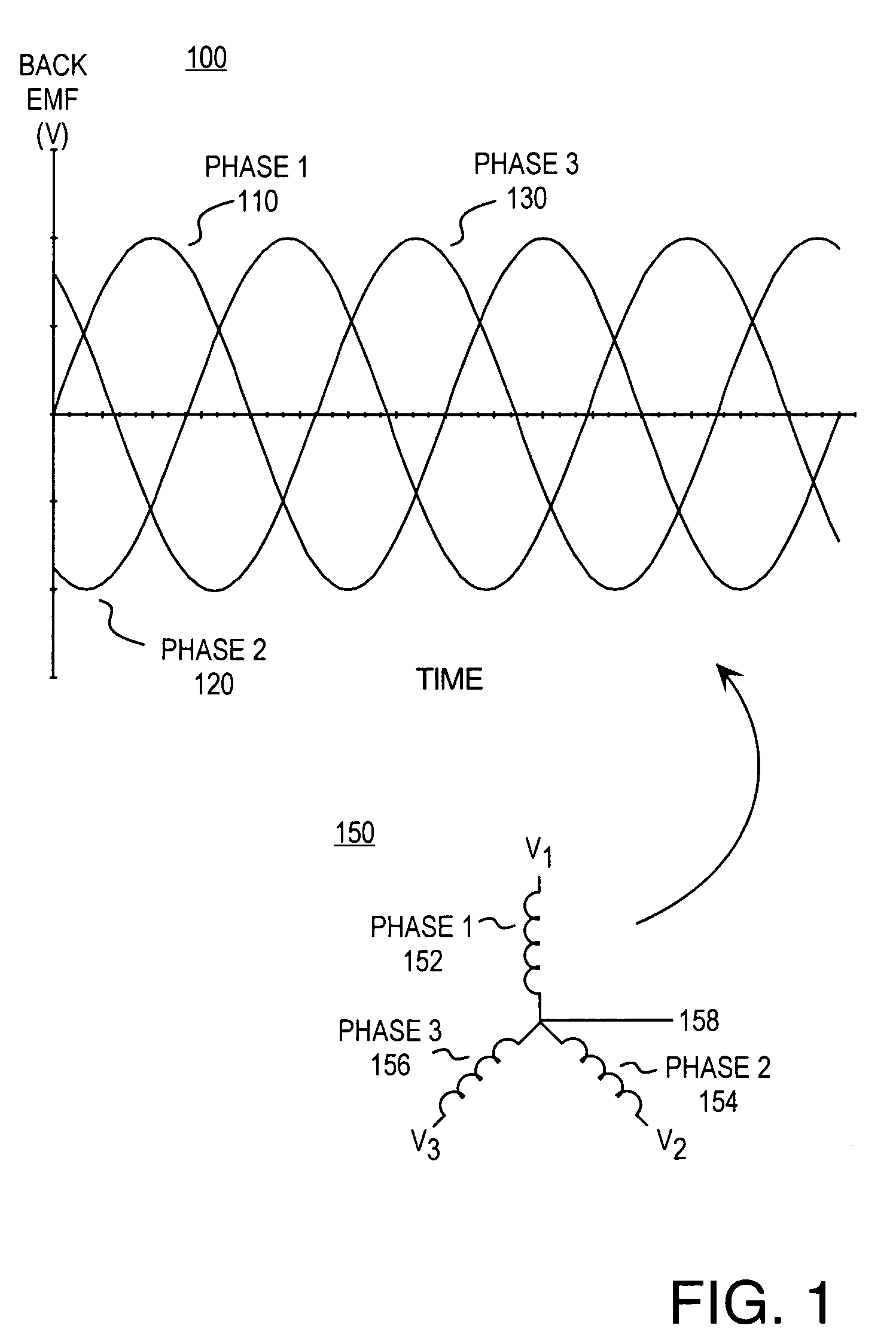
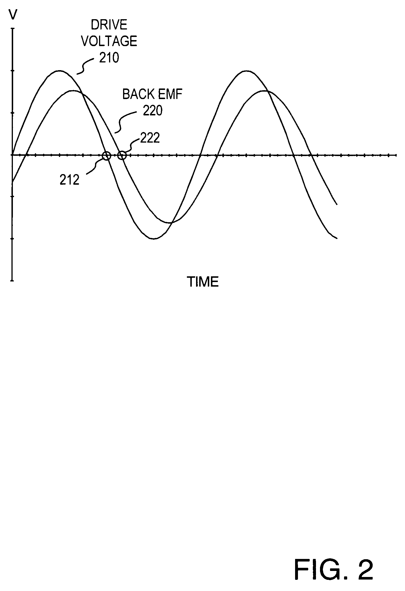
[0009]In view of limitations of known systems and methods, methods and apparatus for controlling a polyphase motor in implantable medical device applications are provided. In one embodiment, the polyphase motor is a brushless DC motor. Various implementations utilize sinusoidal or trapezoidal drive voltages. A method includes the step of sampling the back emf of a selected phase of the motor while the drive voltage of the selected phase is substantially zero. In various embodiments, the sampling interval may or may not straddle a zero crossing of the drive voltage for the selected phase. The sampled back emf provides an error signal indicative of the positional error of the rotor. In one embodiment, the sampled back emf is normalized with respect to a commanded angular velocity of the rotor to provide an error signal proportional only to the positional error of the motor rotor. The error signal is provided as feedback to control a frequency of the drive voltage for commutation control. A speed control generates a speed control signal corresponding to a difference between a commanded angular velocity and an angular velocity inferred from the frequency of the drive voltage. The speed control signal is provided as feedback to control an amplitude of the drive voltage.

Problems solved by technology

Due to the lack of these mechanical commutation components, however, commutation must be provided electrically by the drive electronics.
The center tap is undesirable in medical implant applications because it introduces additional lead wires that must be routed from the pump to the controller.
Both six step drive back emf sensing approaches typically require a phase of the motor to be open-circuited for a large portion of the commutation period and are susceptible to false triggering due to electrical switching noise.
Another disadvantage of six step drive controls is the “on-off” nature of the drive voltage.
The stepping nature of the driving voltage waveform introduces harmonics and electromagnetic noise.
Additionally, the stepping nature of the drive voltage results in increased torque-ripple.
These effects generate acoustical noise and vibration which are undesirable for medical implant applications.
The use of additional sensors in medical implant applications, however, is undesirable as introducing additional cost, complexity, and points of failure for the device.
Disadvantages of this approach include susceptibility to errors in the model, variations in the model due to manufacturing tolerances, and system electrical noise.

Method used


Image

  • Method and apparatus for controlling brushless DC motors in implantable medical devices
  • Method and apparatus for controlling brushless DC motors in implantable medical devices
  • Method and apparatus for controlling brushless DC motors in implantable medical devices

Examples


Embodiment Construction

[0022]Conventional DC (direct current) motors typically have a field system comprising permanent magnets to establish magnetic flux. A commutator is used to distribute current to a plurality of coils or windings on an armature. The commutator is in contact with a plurality of brushes coupled to a power supply. The commutator ensures that current is distributed to the windings in a manner that creates a torque resulting in rotation of the motor's rotor. As the rotor turns, the commutator changes the current distribution to maintain torque. Generally, the commutation of a conventional DC motor is achieved mechanically through the use of slip rings and brushes.

[0023]Brushless DC motors are distinguished from conventional DC motors by the lack of brushes, slip rings, or other mechanical commutators. Commutation for brushless DC motors is provided electronically rather than mechanically. The brushless DC motor is also referred to as a brushless permanent magnet (PM) motor or an AC (alter...


PUM


Abstract

Methods and apparatus for controlling a polyphase motor in implantable medical device applications are provided. In one embodiment, the polyphase motor is a brushless DC motor. The back emf of a selected phase of the motor is sampled while a drive voltage of the selected phase is substantially zero. Various embodiments utilize sinusoidal or trapezoidal drive voltages. The sampled back emf provides an error signal indicative of the positional error of the rotor. In one embodiment, the sampled back emf is normalized with respect to a commanded angular velocity of the rotor to provide an error signal proportional only to the positional error of the motor rotor. The error signal is provided as feedback to control a frequency of the drive voltage. A speed control generates a speed control signal corresponding to a difference between a commanded angular velocity and an angular velocity inferred from the frequency of the drive voltage. The speed control signal is provided as feedback to control an amplitude of the drive voltage. In one embodiment, an apparatus includes a brushless DC motor and a commutation control. The commutation control provides a commutation control signal for a selected phase of the motor in accordance with a sampled back electromotive force (emf) of that phase. The back emf of the phase is sampled only while the corresponding drive voltage for the selected phase is substantially zero, wherein a frequency of a drive voltage of the motor is varied in accordance with the commutation control signal.

Description

FIELD OF THE INVENTION[0001]This invention relates to the field of implantable medical devices. In particular, this invention is drawn to reducing noise and vibration in motor-driven implantable medical device applications.BACKGROUND OF THE INVENTION[0002]Implantable medical devices such as ventricular assist devices are being developed for long term treatment of chronic heart failure. Such devices require a pumping mechanism to move blood. Due to the nature of the application, the pumping mechanism must be highly reliable. Patient comfort is also a significant consideration.[0003]Electrically powered pumping mechanisms typically rely on a motor such as a brushless DC motor. Brushless DC motors offer maintenance advantages in implant applications due to the lack of wear-prone brushes and slip rings. Due to the lack of these mechanical commutation components, however, commutation must be provided electrically by the drive electronics. In order to provide proper commutation, the mecha...

Claims


Application Information

Patent Timeline
Patent Type & Authority Patents(United States)
IPC IPC(8): H02K23/04G05B11/28G05B21/02H02K13/14H02K21/12A61M1/10A61M1/12H02P6/10H02P6/16H02P6/18
CPCH02P6/10H02P6/182H02P2209/07H02P6/18
Inventor GAUTHIER, RAYMOND G.LANCISI, DAVID M.MORRIS, GREGORY L.
Owner HEARTWARE INC
Learn More