Apparatus and method for independent control of on-die termination for output buffers of a memory device

a memory device and output buffer technology, applied in the direction of digital storage, pulse technique, reliability increasing modifications, etc., can solve the problems of negative impact on the performance of the memory device, the time difference at which a signal is received along the length of the signal line, and the timing skew between the signals that are provided

Inactive Publication Date: 2006-11-21
ROUND ROCK RES LLC
View PDF17 Cites 101 Cited by
  • Summary
  • Abstract
  • Description
  • Claims
  • Application Information

AI Technical Summary

Problems solved by technology

Subtle variations in signal timing and operating conditions can negatively impact memory device performance.
These different lengths can cause timing skews between the signals that are provided in parallel to the memory devices and the memory controller, such as data signals and strobe signals.
Additionally, due to propagation delays of a signal line, a time difference at which a signal is received along the length of the signal line will result.
However, in high-speed memory systems, several picoseconds can significantly reduce the timing margin of signals.
As the timing margin of signals decreases, subtle timing variations caused by other factors, such as variations and drifts in power, voltage, and temperature, may result in memory errors.
Moreover, the timing of the signals provided to the memory devices by the memory controller can be skewed relative to one another because of the length of the signal lines and the manner in which the signal is provided to the memory devices.
In practicing the write levelization process with conventional memory devices, a problem results for memory systems having more than one rank of memory devices.
Thus, the ODT for the data strobe buffers cannot be enabled while the ODT for the data buffers are disabled, and vice-versa.

Method used


Image

  • Apparatus and method for independent control of on-die termination for output buffers of a memory device
  • Apparatus and method for independent control of on-die termination for output buffers of a memory device
  • Apparatus and method for independent control of on-die termination for output buffers of a memory device

Examples


Embodiment Construction

[0022]Certain details are set forth below to provide a sufficient understanding of the invention. However, it will be clear to one skilled in the art that the invention may be practiced without these particular details. In other instances, well-known circuits, control signals, timing protocols, and software operations have not been shown in detail in order to avoid unnecessarily obscuring the invention.

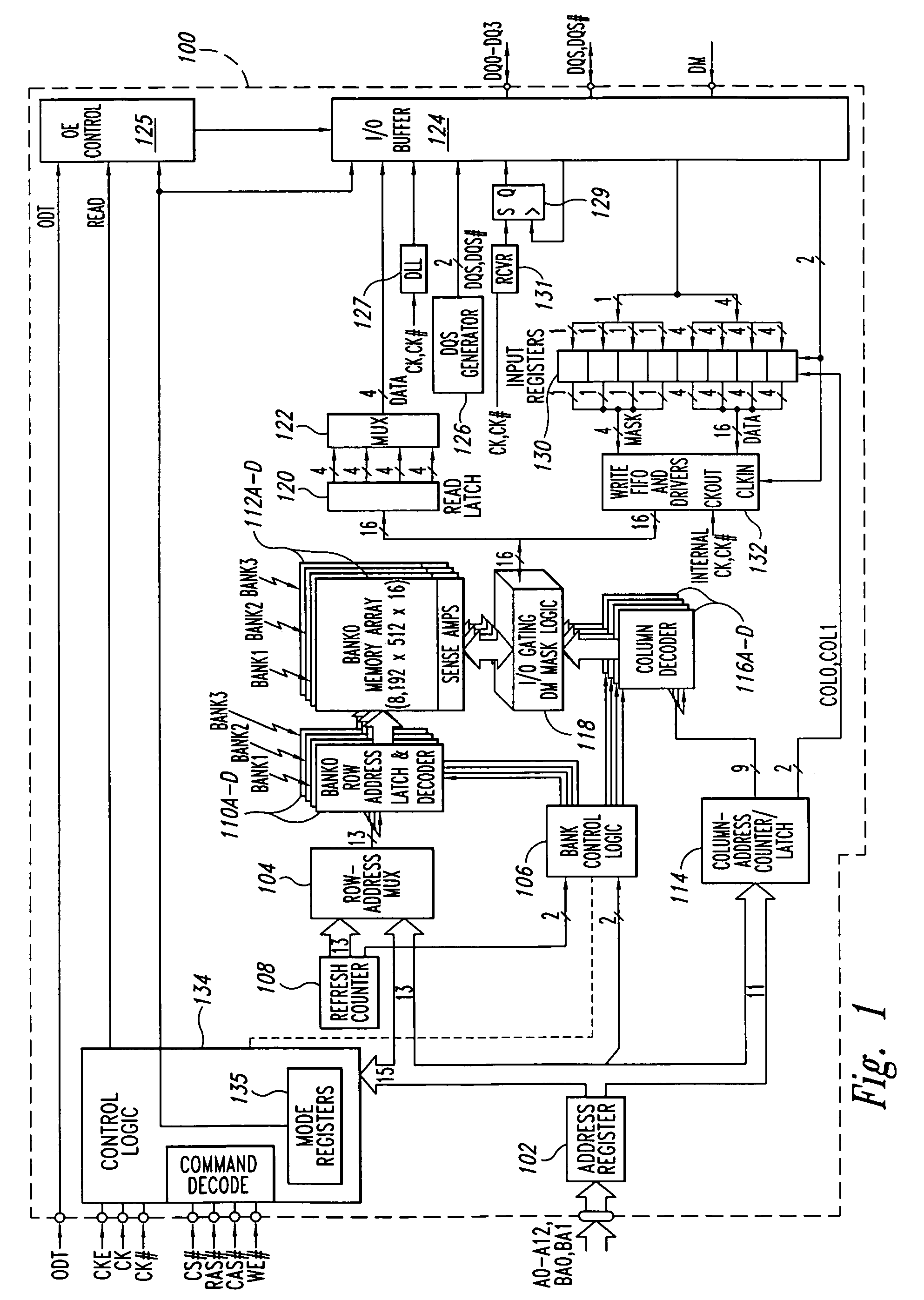
[0023]FIG. 1 illustrates a memory device in which an embodiment of the present invention is implemented. The memory device 100 in FIG. 1 is a double-data rate (DDR) synchronous dynamic random access memory (“SDRAM”). The memory device 100 is referred to as a double-data-rate device because the data words DQ being transferred to and from the device are transferred at double the rate of a conventional SDRAM, which transfers data at a rate corresponding to the frequency of the applied clock signal. However, the principles described herein are applicable to any memory device that may incl...


PUM


Abstract

An apparatus and method providing independent control of on-die termination (ODT) of output buffers. The ODTs for the buffer circuits of an input / output (I / O) buffer can be enabled and disabled in response to an ODT control signal. Additionally, the ODTs for a first set of the buffer circuits can be enabled and disabled responsive to the ODT control signal and the ODT for at least one of a second set of the buffer circuits is disabled.

Description

TECHNICAL FIELD[0001]The present invention relates generally to semiconductor memory devices, and more specifically, to memory devices having independent control of on-die termination circuits of buffer circuits, such as data strobe and data buffers.BACKGROUND OF THE INVENTION[0002]Memory devices are typically assembled into memory modules that are used in a computer system. These memory modules typically include single in-line memory modules (SIMMs) having memory devices on one side of the memory module, and dual in-line memory modules (DIMMs) having memory devices on both sides of the memory module. The memory devices of a memory module are accessed in groups. Each of the groups are commonly referred to as “ranks,” with single-sided DIMMs typically having one rank of memory devices and double-sided DIMMs having two ranks of memory devices, one rank on either side of the memory module.[0003]Each of the memory devices of a memory module receives a set of signals which is generated b...

Claims


Application Information

Patent Timeline
Patent Type & Authority Patents(United States)
IPC IPC(8): H03K17/16
CPCG11C7/1051G11C7/1057H03K19/00323
Inventor JANZEN, JEFFLI, WEN
Owner ROUND ROCK RES LLC
Why Eureka
Try Eureka