Head drum assembly of a tape recorder having a resilient body to preload bearings thereof

a tape recorder and resilient body technology, applied in the direction of mounting head within the housing, recording information storage, instruments, etc., can solve the problems of difficult control of preload, poor quality, increase in manufacturing cost, etc., to improve bearing preloading method and structure, reduce manufacturing cost, and improve the effect of assembling efficiency

Inactive Publication Date: 2006-11-21
SAMSUNG ELECTRONICS CO LTD
View PDF37 Cites 4 Cited by
  • Summary
  • Abstract
  • Description
  • Claims
  • Application Information

AI Technical Summary

Benefits of technology

[0021]The present invention has been developed in order to solve the above problems in the related art. Accordingly, a first embodiment of the present invention provides a head drum assembly of a tape recorder employing improved bearing preloading method and structure with a ball bearing having an inner race and an outer race, to provide enhanced assembling efficiency and reduced manufacturing costs.

Problems solved by technology

As the conventional bearing preload construction of the head drum assembly additionally requires the setscrew s for securing the preloading boss 60, the manufacturing cost increases.
Further, because it is not easy to determine the position of the preloading boss 60 for the securing by the setscrew s, it is difficult to control the preload, and this contributes to poor quality, such as noise generation, at the time of driving the bearings.
Therefore, there are problems in that productivity deteriorates and manufacturing costs increase.
As a result, the precise assembling of the bearing assembly cannot be guaranteed, which is a critical disadvantage especially in the field of precision instruments, which is highly sensitive to height variation of the bearing.
However, damage can also occur to the bearings and the upper drum during the assembling process due to narrow gaps between the parts, and accordingly, precise assembling cannot be guaranteed.
Further, the assembling process and control thereof is complicated.
As a result, there is a disadvantage in the above described conventional assembly method of the head drum assembly of a magnetic recording / reproducing apparatus in that the assembling precision of the upper and the lower drum 90 and 92 deteriorates by age hardening.

Method used


Image

  • Head drum assembly of a tape recorder having a resilient body to preload bearings thereof
  • Head drum assembly of a tape recorder having a resilient body to preload bearings thereof
  • Head drum assembly of a tape recorder having a resilient body to preload bearings thereof

Examples


first embodiment

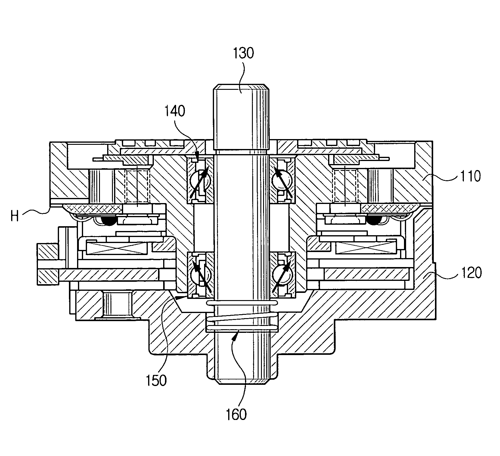
[0081]As shown in FIG. 2, a head drum assembly 100 of a tape recorder according to the present invention includes a rotary drum 110 for rotatably supporting a magnetic head (H) for recording / reproducing information by scanning a running magnetic tape, a stationary drum 120 press-fitted onto a lower portion of a shaft 130 engaged in an axial bore of the rotary drum 110, parallel to the rotary drum 110, an upper bearing 140 and a lower bearing 150 located one on the other between the rotary drum 110 and the shaft 130, and a resilient body 160 acting as a preload means for applying a preload to the lower bearing 150, wherein the resilient body 160 is disposed between the stationary drum 120 and the lower bearing 150 and mounted on an outer circumference of the shaft 130 to upwardly bias an inner race 151 of the lower bearing 150.

[0082]The head drum assembly of the tape recorder according to an embodiment of the present invention employs a ball bearing supporting a plurality of balls to...

second embodiment

[0090]Referring to FIGS. 4 and 5, the head drum assembly 200 according to the present invention includes a rotary drum 210 rotatably disposed on a shaft 240 to support a magnetic head (H) for recording / reproducing information by scanning a running magnetic tape, a drum cover 230 and a stationary drum 220 press-fitted to the shaft 240 and positioned upper and lower sides with respect to the rotary drum 210 which is interposed therebetween, an upper bearing 250 and a lower bearing 260 disposed one on the other between the rotary drum 210 and the shaft 240, and a resilient body 270 disposed between the drum cover 230 and the upper bearing 250 to downwardly bias an inner race 251 of the upper bearing 250.

[0091]The upper bearing 250 and the lower bearing 260 are a typical small-sized ball bearing which are provided with steel balls (see B of FIG. 5) interposed between the inner race 251, 261 and the outer race 252, 262. Reference numerals 211 and 212 indicate a motor rotor and a motor st...

third embodiment

[0104]FIG. 7 is a view illustrating a head drum assembly according to the present invention, which includes a bearing assembly 335, an upper drum 336, a magnetic head 340, a rotary transformer 339, a cover drum 337 and a motor drum rotor 341.

[0105]The bearing assembly 335 is provided to the inner center of the head drum assembly, and includes a shaft 325, a spring 320, an upper bearing 314 and a lower bearing 316.

[0106]The shaft 325 has three grooves formed in the upper and lower ends, respectively, and these will be described in greater detail below. Upper and lower bearings 314, 316 are press-fitted to the upper and lower ends of the shaft 325, and a coil spring 320 is inserted between the upper and lower bearings 314, 316. An end of the coil spring 320 is inserted to a hole 316a defined in an outer race 319 of the upper and lower bearings 314, 316 to apply preload to the upper and lower bearings 314, 316.

[0107]The upper drum 336, which is rotatable, and the lower drum 338, which ...


PUM

PropertyMeasurementUnit
temperatureaaaaaaaaaa
diameteraaaaaaaaaa

Abstract

A head drum assembly of a tape recorder in which an inner race and an outer race of an upper bearing are press-fitted onto a shaft and a rotary drum, respectively, thereby applying a preload. A resilient body, such as a compressed coil spring, is disposed between a lower bearing disposed between the rotary drum and the shaft and a stationary drum. The resilient body upwardly presses the inner race of the lower bearing, thereby applying a preload. Accordingly, the head drum assembly of the tape recorder provides enhanced assembling efficiency and reduced manufacturing costs.

Description

FOREIGN PRIORITY INFORMATION[0001]This application claims priority under 35 U.S.C. § 119 to Korean Patent Application Serial No. 2002-61088, filed in the Korean Intellectual Property Office on Oct. 7, 2002, to Korean Patent Application Serial No. 2002-80911, filed in the Korean Intellectual Property Office on Dec. 17, 2002, to Korean Patent Application Serial No. 2002-65279, filed in the Korean Intellectual Property Office on Oct. 24, 2002, to Korean Patent Application Serial No. 2002-80912, filed in the Korean Intellectual Property Office on Dec. 17, 2002 and to Korean Patent Application Serial No. 2003-9514, filed in the Korean Intellectual Property Office on Feb. 14, 2003, the contents of all five said applications being incorporated herein by reference.BACKGROUND OF THE INVENTION[0002]1. Field of the Invention[0003]The present invention relates to a head drum assembly of a tape recorder such as a VCR, a camcorder and a DVC (Digital Video Camera), and more particularly, to a head...

Claims


Application Information

Patent Timeline
Patent Type & Authority Patents(United States)
IPC IPC(8): G11B5/52F16C25/08G11B5/105G11B5/53
CPCG11B5/105G11B5/537
Inventor LEE, SEUNG-WOOHONG, SUNG-HEEKANG, TAE-GILCHOI, DO-YOUNGBAIK, CHUNG-HUM
Owner SAMSUNG ELECTRONICS CO LTD
Why Eureka
Try Eureka