Magnetic head and production method for magnetic heads

a production method and magnetic head technology, applied in the field of magnetic head, can solve the problems of significant deterioration in the quality of read-back signals, short circuit of the output terminal, and increase of the read-back noise, so as to improve the efficiency of inducing magnetic flux, simple production method, and simple structure

Inactive Publication Date: 2006-11-28
HITACHI LTD
View PDF14 Cites 13 Cited by
  • Summary
  • Abstract
  • Description
  • Claims
  • Application Information

AI Technical Summary

Benefits of technology

[0018]The present invention aims may enhance the efficiency of inducing magnetic fluxes to the MR element by a flux guide through the use of magnetic shields of a simpler structure and a simpler production method which thereby reduce the ou

Problems solved by technology

Where an MR element of such a fine structure is to be used, if its tip is directly exposed on the air bearing surface (head flying surface), the outlet terminals may become short-circuited during the grinding process undertaken to expose the MR element or by dust accumulating on the medium.
If the outlet terminals are short-circuited in this way, the rate of resistance change of the MR element will drop heavily or the read-back noise may increase, both of which may result in a significant deterioration in the quality of the read-back signals.
The short-circuiting problem is particularly acute with this TMR element.
A disadvantage in utilizing the flux guide structure lies in the insufficient magnetic resistance between the flux guide and magnetic shields sandwiching it.
However, even in these improved structures according to the prior art, the magnetic shields are formed in a direction substantially parallel to the flux guide, i.e.

Method used


Image

  • Magnetic head and production method for magnetic heads
  • Magnetic head and production method for magnetic heads
  • Magnetic head and production method for magnetic heads

Examples


Embodiment Construction

[0050]It is to be understood that the figures and descriptions of the present invention have been simplified to illustrate elements that are relevant for a clear understanding of the present invention, while eliminating, for purposes of clarity, other elements that may be well known. Those of ordinary skill in the art will recognize that other elements are desirable and / or required in order to implement the present invention. However, because such elements are well known in the art, and because they do not facilitate a better understanding of the present invention, a discussion of such elements is not provided herein. The detailed description will be provided hereinbelow with reference to the attached drawings.

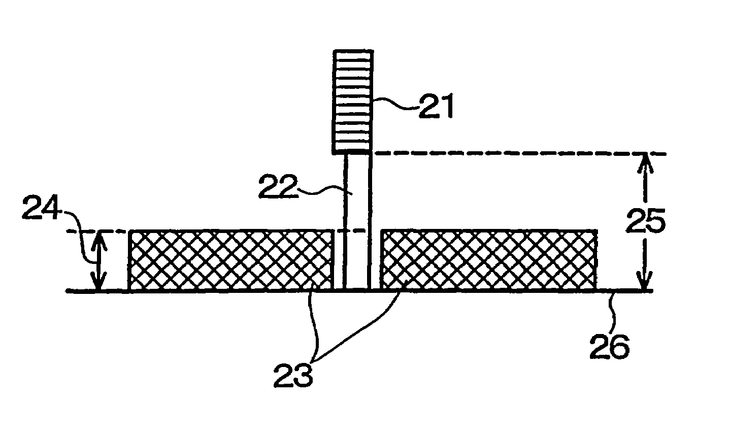
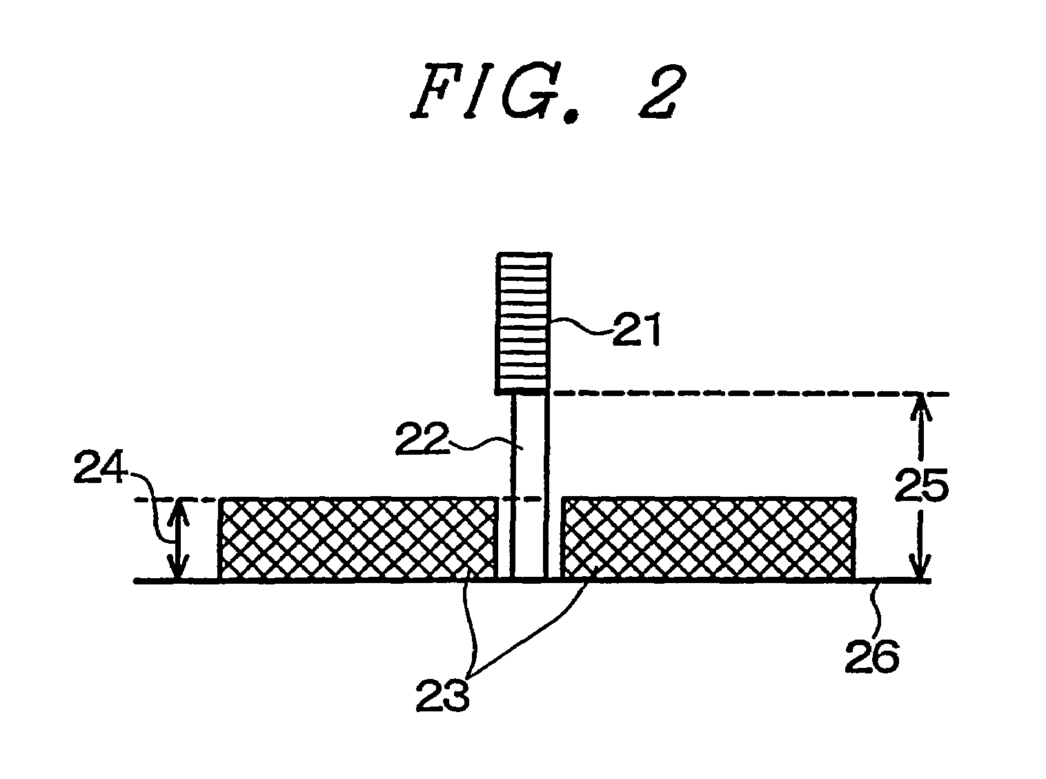
[0051]Preferred embodiments of the present invention will be generally outlined first. According to the invention, at least in the vicinity of a flux guide, magnetic shields are formed in parallel to the air bearing surface of the head, and the height of the magnetic shields i...


PUM

PropertyMeasurementUnit
Heightaaaaaaaaaa
Sensitivityaaaaaaaaaa

Abstract

Magnetic heads capable of recording and reading with high sensitivity and resolution are provided by minimizing the outflow of magnetic fluxes from a flux guide to magnetic shields while using a flux guide structure for an MR element. In the magnetic head, magnetic shields exposed on a surface opposite a magnetic recording medium (air bearing surface) and a flux guide exposed between the magnetic heads via a non-magnetic layer are provided, and magnetic fluxes are guided by the flux guide to a magnetoresistive (MR) element formed in a position not exposed on the air bearing surface. The height of the magnetic shields in direction perpendicular to the air bearing surface is less than the distance from the air bearing surface to the MR element.

Description

PRIORITY TO FOREIGN APPLICATIONS[0001]This application is Continuation of nonprovisional application Ser. No. 09 / 920,664 filed Aug. 3, 2001 now U.S. Pat. No. 6,665,152, Priority is claimed based on U.S. application Ser. No. 09 / 920,664 filed Aug. 3, 2001, which claims the priority of Japanese application 2001-093053 filed on Mar. 28, 2001.BACKGROUND OF THE INVENTION[0002]1. Field of the Invention[0003]The present invention relates to a magnetic head for recording and / or reading back information in an apparatus using a magnetic recording medium which holds information according to magnetic changes in a magnetic recording film formed over the surface of the medium, and more particularly, the invention relates to the structure of a magnetoresistive thin film magnetic head capable of high-sensitivity and high-resolution recording and reading back, and a production method therefor.[0004]2. Description of the Background[0005]In recent years, there has been rapid progress made-in high-densi...

Claims


Application Information

Patent Timeline
IPC IPC(8): G11B5/127H04R31/00G11B5/00G11B5/02G11B5/10G11B5/265G11B5/31G11B5/39G11B11/10H01L43/08
CPCB82Y10/00G11B5/127G11B5/3103G11B5/3903G11B5/3909G11B5/3916G11B5/3967B82Y25/00Y10T29/49041G11B5/10G11B2005/0005G11B2005/0021Y10T29/49044Y10T29/49048Y10T29/49052Y10T29/49798Y10T29/49037Y10T29/49043Y10T29/49046
Inventor NEMOTO, HIROAKI
Owner HITACHI LTD
Why Eureka
Try Eureka