Method and apparatus for drilling with casing

a casing and drilling technology, applied in the direction of drilling pipes, drilling well accessories, sealing/packing, etc., can solve the problems of increasing the possibility of downtime, increasing the likelihood of thread damage, and time-consuming process of connecting and disconnecting a casing, so as to achieve safer drilling operation and less cost

Inactive Publication Date: 2006-11-28
WEATHERFORD TECH HLDG LLC
View PDF798 Cites 95 Cited by
  • Summary
  • Abstract
  • Description
  • Claims
  • Application Information

AI Technical Summary

Benefits of technology

[0038]Providing apparatus and methods for pivoting from the axial line including the top drive on the rails eliminates the need for cable bails with single joint elevators attached thereto to transport the casing string to well center. As such, moving the casing string to well center for a pipe handling operation or drilling with casing operation is safer and thus less expensive as well as more efficient.

Problems solved by technology

However, the process of connecting and disconnecting a casing is time consuming.
Furthermore, this process also increases the likelihood of damage to the threads, thereby increasing the potential for downtime.
Because the free end of the casing is unsupported, this task generally presents a hazard to the personnel on the rig floor as they try to maneuver the casing above the wellbore.
While the spinner provides a faster make up rate, it fails to provide enough torque to form a fluid tight connection.
Whereas the power tong may provide enough torque, it fails to make up the connection in an efficient manner because the power tong must grip the casing several times to tighten the connection.
Because operating time for a rig is very expensive, some as much as $500,000 per day, there is enormous pressure to reduce the time they are used in the formation of the wellbore.

Method used


Image

  • Method and apparatus for drilling with casing
  • Method and apparatus for drilling with casing
  • Method and apparatus for drilling with casing

Examples


first embodiment

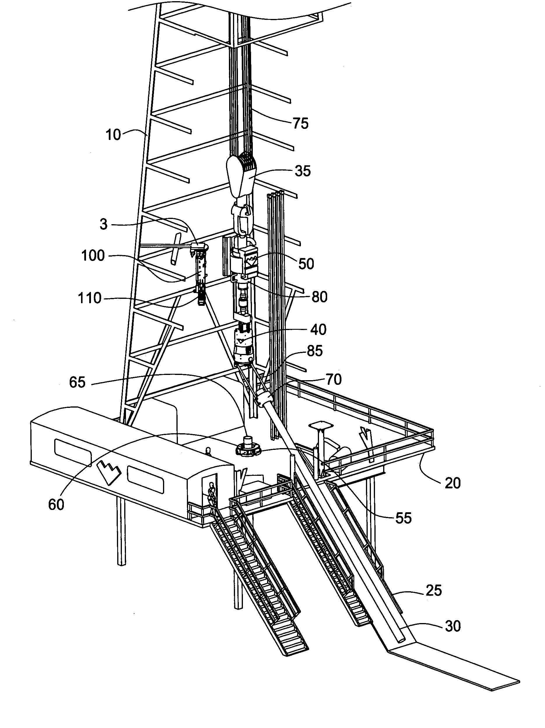
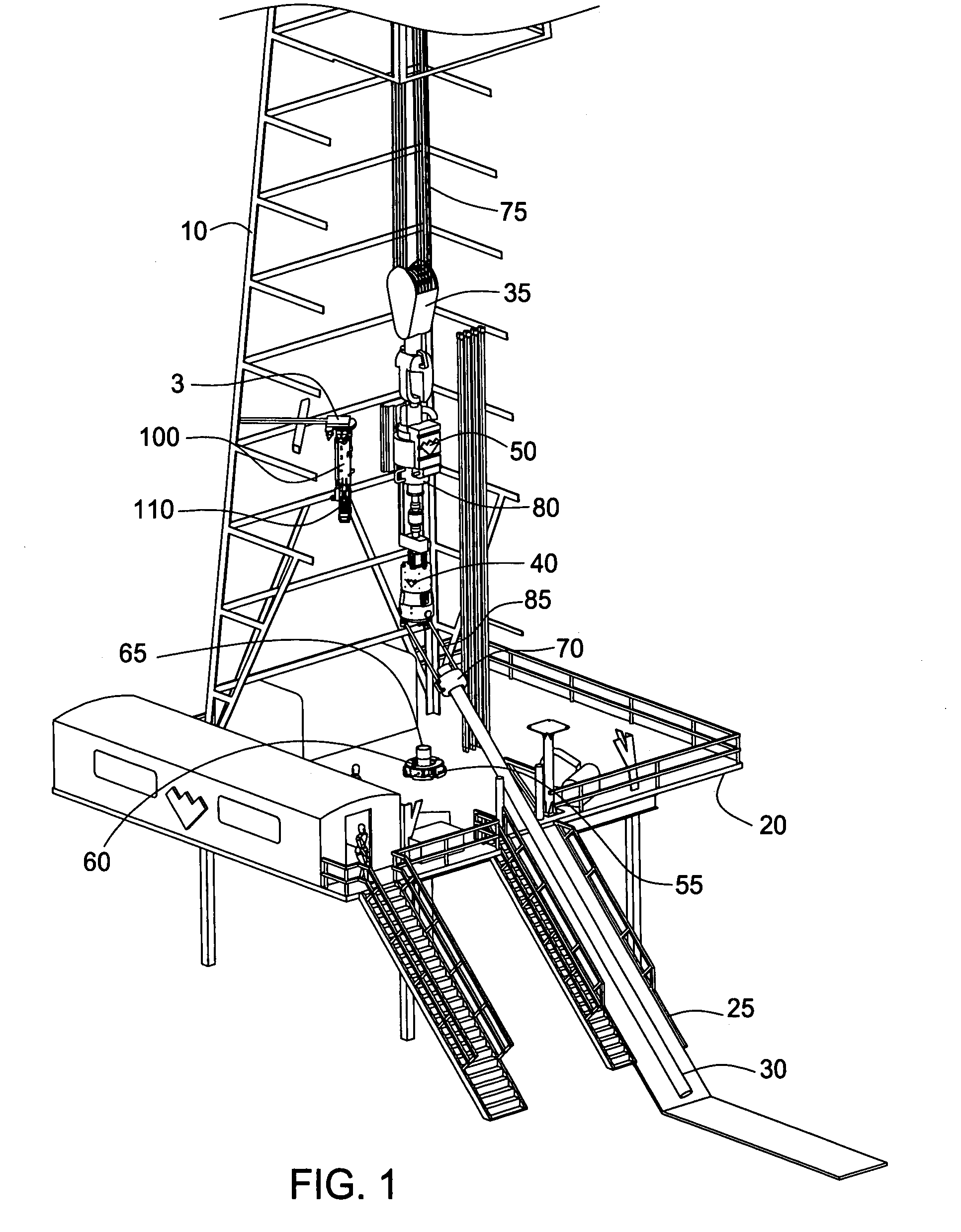
[0108]The operation of the first embodiment is shown in FIGS. 9–13. In FIG. 9, the casing string 65 which was previously drilled into the formation (not shown) to form the wellbore (not shown) is shown disposed within the hole 55 in the rig floor 20. The casing string 65 may include one or more joints or sections of casing threadedly connected to one another. Operatively connected at a lower end of the casing string 65 is an earth removal member, such as a drill bit (not shown), which is used to drill through the formation to form the wellbore. The casing string 65 is hindered from downward movement into the wellbore by the spider 60, as the gripping members or slips of the spider 60 are engaged around the outer diameter of the casing string 65. The casing string 65 is also rotationally fixed relative to the rig floor 20 by the spider 60.

[0109]Initially, the traveling block 35, top drive 50, pivotable mechanism 345, and torque head 40 are located substantially coaxially with and in ...

third embodiment

[0127]The operation of the present invention shown in FIG. 18 is very similar to the operation of the embodiments depicted in FIGS. 9–17, so like parts are labeled with like numbers. This embodiment, however, lacks the pivotable mechanism 345 which is present in FIGS. 9–17. The top drive 50 is connected to the torque head 40 so that the two are substantially coaxial and located within the same plane. A swivel joint (not shown) is preferably located between the top drive 50 and torque head 40 so that the torque head 40 is allowed to transmit torque more efficiently and effectively to the casing 30 relative to top drive 50.

[0128]Instead of the pivotable mechanism 345 tilting outward from well center to pick up the casing 30 from the rack 25, the telescopic links 391 pivot relative to the torque head 40, which is rigidly longitudinally fixed above well center, as shown in FIG. 18. Initially, the telescopic links 391 are unactuated so that the pistons 393 are located within the cylinder...


PUM


Abstract

Methods and apparatus for drilling with a top drive system are provided. In one aspect, a top drive system includes a top drive, top drive adapter, and a tubular positioning apparatus. In another aspect, the top drive adapter is pivotably connected to the top drive for pivoting the top drive adapter toward the casing string with respect to the top drive. In another aspect, the system includes a telescopic link system connected to a lower portion of the top drive adapter to move the casing string into engagement with the top drive adapter. In another aspect, the top drive adapter includes a housing operatively connected to the top drive and a plurality of retaining members disposed in the housing for gripping the tubular. In another aspect, the tubular positioning apparatus includes a gripping member for engaging a tubular and a conveying member for positioning the gripping member. A spinner may be provided to rotate the tubular.

Description

CROSS-REFERENCE TO RELATED APPLICATIONS[0001]This application claims benefit of U.S. Provisional Patent Application Ser. No. 60 / 452,318, filed Mar. 5, 2003, which application is herein incorporated by reference in its entirety.[0002]This application also claims benefit of U.S. Provisional Patent Application Ser. No. 60 / 451,965, filed Mar. 5, 2003, which application is herein incorporated by reference in its entirety.[0003]This application is a continuation-in-part of U.S. patent application Ser. No. 10 / 382,353, filed on Mar. 5, 2003 and published as U.S. Patent Application Publication No. 2004 / 0003490 on Jan. 8, 2004, which application is a continuation-in-part of U.S. patent application Ser. No. 09 / 486,901, filed on May 19, 2000, which issued as U.S. Pat. No. 6,591,471 on Jul. 15, 2003, which is the National Stage of International Application No. PCT / GB98 / 02582, filed on Sep. 2, 1998, and published under PCT article 21(2) in English, which claims priority of United Kingdom Applicat...

Claims


Application Information

Patent Timeline
Patent Type & Authority Patents(United States)
IPC IPC(8): E21B19/16E21BE21B3/02E21B7/20E21B19/06E21B19/07E21B19/14
CPCE21B7/20E21B19/14E21B19/161
Inventor SHAHIN, DAVIDHABETZ, JEFFHAUGEN, DAVID M.THOMPSON, GARYPIETRAS, BERND-GEORGHOLLINGSWORTH, JIMMY L.REINHOLDT, BERND
Owner WEATHERFORD TECH HLDG LLC
Why Eureka
Try Eureka