Polishing apparatus

a technology of polishing apparatus and substrate, which is applied in the direction of edge grinding machines, manufacturing tools, lapping machines, etc., can solve the problems of substrate polishing apparatus, negative effect on production capacity, and affect the apparatus as a whole, and achieve the effect of efficient replacement of polishing fluid

Active Publication Date: 2006-11-28
EBARA CORP
View PDF15 Cites 38 Cited by
  • Summary
  • Abstract
  • Description
  • Claims
  • Application Information

AI Technical Summary

Benefits of technology

[0013]As stated above, the polishing apparatus comprises a polishing fluid discharge chamber which is communicated with the polishing fluid supply chamber, and a polishing fluid discharge pipe which is in fluid communication with the polishing fluid discharge chamber. By this arrangement, it is possible to efficiently replace polishing fluid in the polishing fluid chamber, with either fresh polishing fluid (slurry) or pure water, as required. By discharging polishing fluid or pure water from the discharge chamber through the discharge pipe it is further possible to prevent polishing fluid and pure water from being mixed within the supply chamber.

Problems solved by technology

A conventional substrate polishing apparatus suffers from a problem in that the substrate carrier for holding a substrate to be polished vibrates during a polishing operation.
This vibration is caused by a frictional force generated between the substrate and polishing surfaces when polishing liquid is not supplied appropriately.
This vibration affects the apparatus as a whole, and has a negative effect on production capacity.
It also generates noise in a work environment.
A further problem with this prior art apparatus is that it consumes as much as 200 ml / min of slurry as polishing fluid, which makes substrate polishing operations expensive.

Method used


Image

  • Polishing apparatus
  • Polishing apparatus
  • Polishing apparatus

Examples


Embodiment Construction

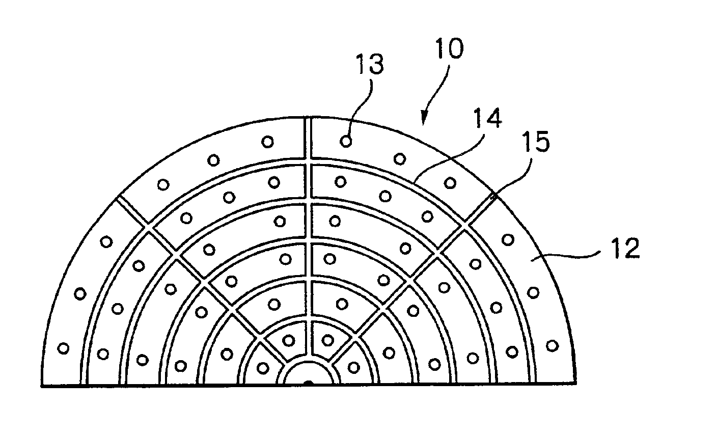
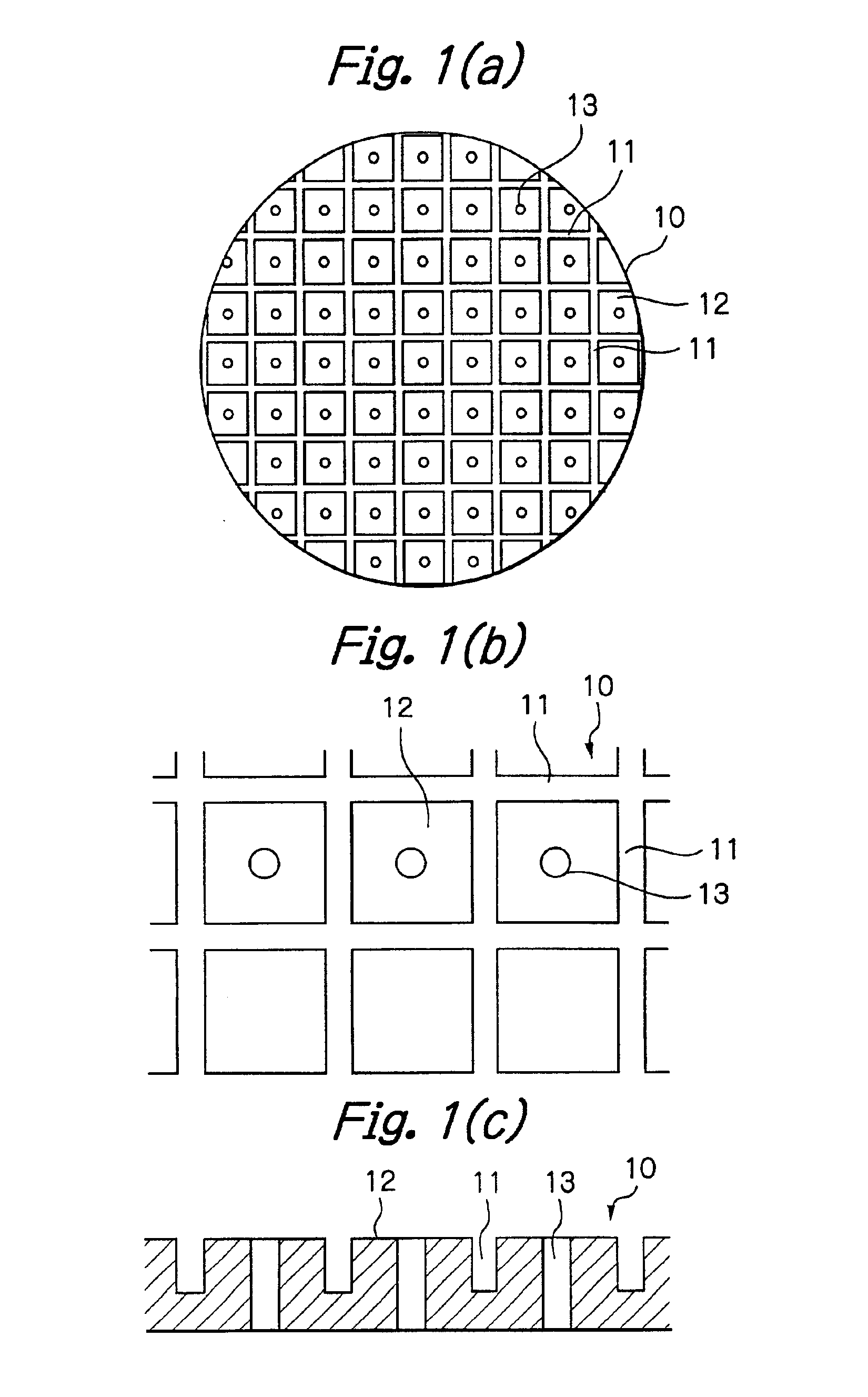
[0024]An embodiment of the present invention will now be explained with reference to the drawings. FIG. 1(a) is a plan view of a polishing pad to be placed on a polishing table of a polishing apparatus according to this invention. FIG. 1(b) is a partial enlarged view of the pad, and FIG. 1(c) is a partial sectional view. A polishing pad 10 is adhesively mounted on an upper surface of a polishing table and functions as a polishing surface. A plurality of grooves 11 are formed in the polishing pad 10. The grooves 11 extend at right angles relative to one another so as to form a plurality of lands 12. A plurality of openings 13 are centrally formed in respective lands 12 that open into an upper surface (polishing surface) of the polishing pad 10.

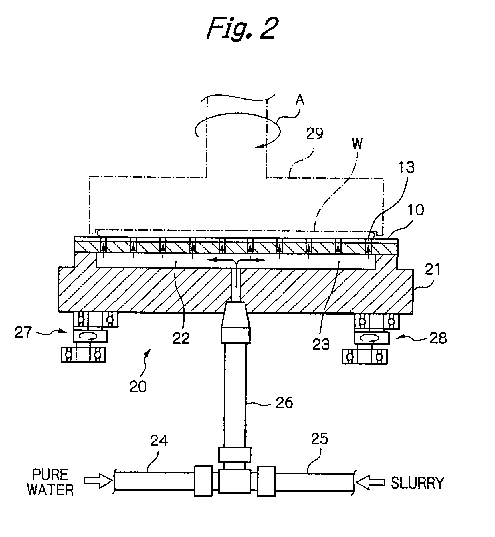
[0025]FIG. 2 is a schematic view, partly in section of a polishing apparatus according to one embodiment of the present invention. The polishing apparatus 20 includes a polishing table 21 on which the polishing pad 10 is adhesively mounted. A c...


PUM


Abstract

A polishing apparatus includes a plurality of polishing fluid supply openings terminating in a polishing surface of a polishing table, and a plurality of grooves which are formed in the polishing surface and arranged so as not to be in direct communication with the polishing fluid supply openings. The polishing apparatus further includes a polishing fluid supply system for supplying a polishing fluid to a surface of a substrate through the openings. The grooves may extend at right angles relative to one another so as to define a plurality of lands therebetween, and the polishing fluid supply openings are formed through the lands.

Description

BACKGROUND OF THE INVENTION[0001]This invention relates to a substrate polishing apparatus for polishing a surface of a substrate, including a semiconductor wafer, and operates by pressing a surface of a substrate to be polished against a polishing surface of a polishing table, and effecting a relative motion between these respective surfaces.[0002]Conventional substrate polishing apparatuses comprise: a polishing table; a polishing pad, which functions as a polishing surface, provided on an upper surface of the polishing table; and a substrate carrier for holding a substrate to be polished. During a polishing operation, a substrate is held in place by the substrate carrier, and a surface of the substrate to be polished is pressed against the polishing surface of the polishing table, with relative motion being effected between these respective surfaces while a polishing fluid is supplied to the polishing surface.[0003]Recent advances in semiconductor technology, including integratio...

Claims


Application Information

Patent Timeline
Patent Type & Authority Patents(United States)
IPC IPC(8): B24B5/00B24D15/00B24B7/22B24B37/00B24B37/12B24B37/16B24B55/02B24B57/02H01L21/304
CPCB24B37/26B24B57/02
Inventor NABEYA, OSAMU
Owner EBARA CORP
Why Eureka
Try Eureka