
Method and apparatus for a body fluid sampling device using illumination

a body fluid and illumination technology, applied in the field of methods and apparatus for body fluid sampling devices, can solve the problems of multiple strikes due to recoil, patient compliance, and discourage patients from testing, and achieve the effect of high density design

Inactive Publication Date: 2006-11-28
SANOFI AVENTIS DEUT GMBH
View PDF39 Cites 167 Cited by
  • Summary
  • Abstract
  • Description
  • Claims
  • Application Information

AI Technical Summary

Benefits of technology

[0007]The present invention provides solutions for at least some of the drawbacks discussed above. Specifically, some embodiments of the present invention provide a multiple lancet solution to measuring analyte levels in the body. The invention may use a h...

Problems solved by technology

Unfortunately, the pain associated with each lancing event using known technology discourages patients from testing.
In addition to vibratory stimulation of the skin as the driver impacts the end of a launcher stop, known spring based devices have the possibility of firing lancets that harmonically oscillate against the patient tissue, causing multiple strikes due to recoil.
This recoil and multiple strikes of the lancet is one major impediment to patient compliance with a structured glucose monitoring regime.
Another impediment to patient compliance is the lack of spontaneous blood flow generated by known lancing technology.
In addition to the pain as discussed above, a patient may need more than one lancing event to obtain a blood sample since spontaneous blood generation is unreliable using known lancing technology.
Known devices poorly account for these skin thickness variations.
A still further impediment to improved compliance with glucose monitoring are the many steps and inconvenience associated with each lancing event.
The large number of steps required in traditional methods of glucose testing, ranging from lancing, to milking of blood, applying blood to a test strip, and getting the measurements from the test strip, discourages many diabetic patients from testing their blood glucose levels as often as recommended.
Older patients and those with deteriorating motor skills encounter difficulty loading lancets into launcher devices, transferring blood onto a test strip, or inserting thin test strips into slots on glucose measurement meters.
Additionally, many devices using a lancet to perform sampling are relatively large compared to the diameter of the lancet.
Exact placement of the lancet may allow reduction of pain due to choosing less sensitive areas of skin, or avoidance of calluses that develop from repetitive sampling, which may reduce the success rate of obtaining blood from the skin.

Method used


Image

  • Method and apparatus for a body fluid sampling device using illumination
  • Method and apparatus for a body fluid sampling device using illumination
  • Method and apparatus for a body fluid sampling device using illumination

Examples


first embodiment

[0160]Referring now to FIGS. 70 and 71, one object for some embodiments of the invention is to include blood sampling and sensing on this penetrating member actuation device. In the present embodiment, the drive mechanism (gripper 738 and solenoid drive coil 739) may be used to drive a penetrating member into the skin and couple this lancing event to acquire the blood sample as it forms at the surface of the finger. In a first embodiment shown in FIG. 70, microfluidic module 740 bearing the analyte detecting member chemistry and detection device 742 (FIG. 71) is couple on to the shaft of the penetrating member 720. The drive cycle described above may also actuate the module 740 so that it rests at the surface of the finger to acquire blood once the penetrating member retracts from the wound. The module 740 is allowed to remain on the surface of the finger or other tissue site until the gripper 738 has reached the back end 744 of the microfluidics module 740, at which point the modul...

embodiment 800

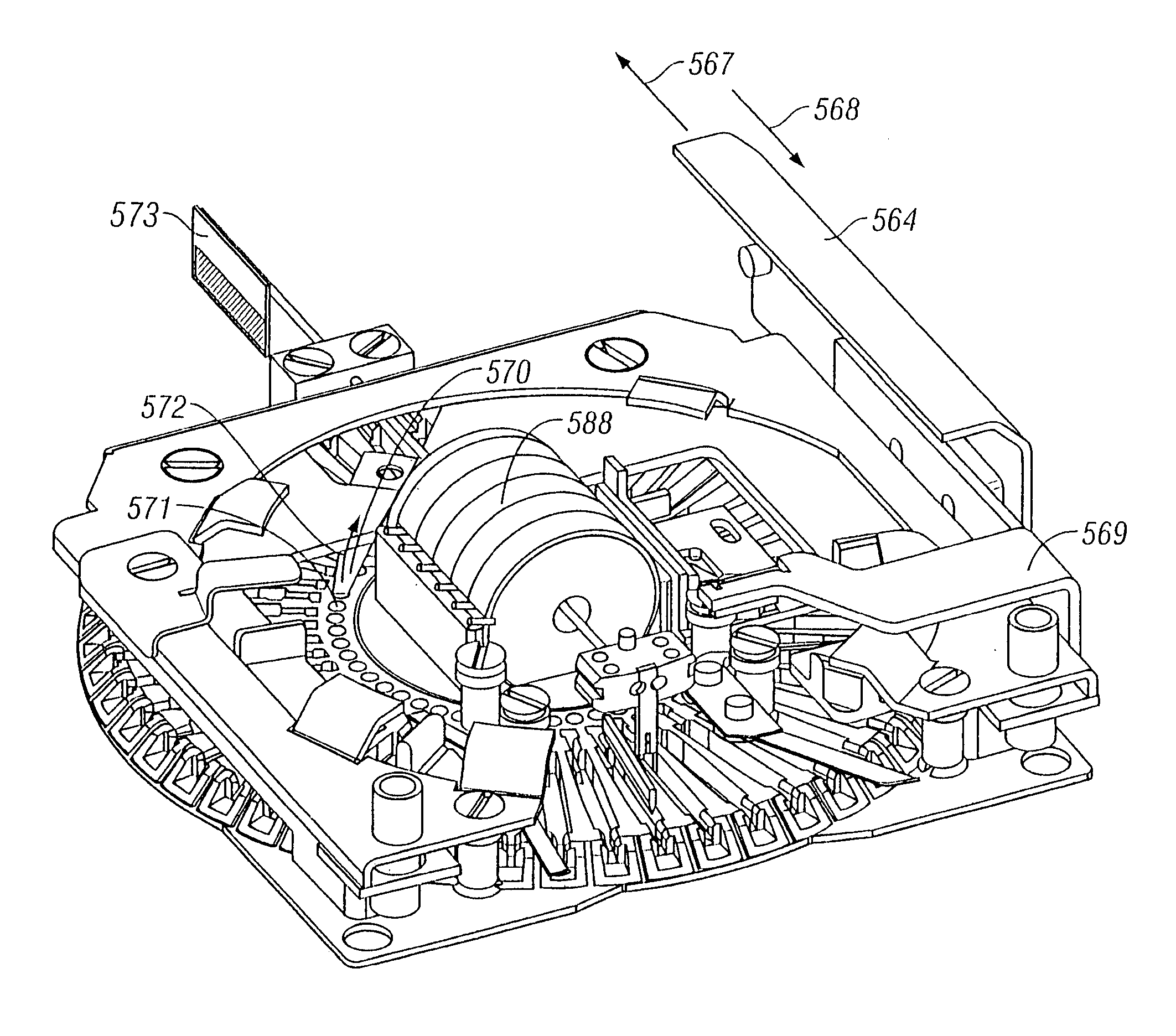
[0182]Referring now to FIG. 87A, the cartridge 500 provides a high density packaging system for a lancing system. This form factor allows a patient to load a large number penetrating members through a single cartridge while maintaining a substantially handheld device. Of course such a cartridge 500 may also be used in non-handheld devices. The present cartridge 500 provide a high test density per volume of the disposable. For embodiments of a cartridge that includes analyte detecting members in addition to penetrating members such as cartridge 800, the density may also be measured in terms of density of analyte detecting members and penetrating members in a disposable. In other embodiments, the density may also be expressed in terms of analyte detecting members per disposable. For example, by taking the physical volume of one embodiment or the total envelope, this number can be divided by the number of penetrating members or number of tests. This result is the volume per penetrating...


PUM


Abstract

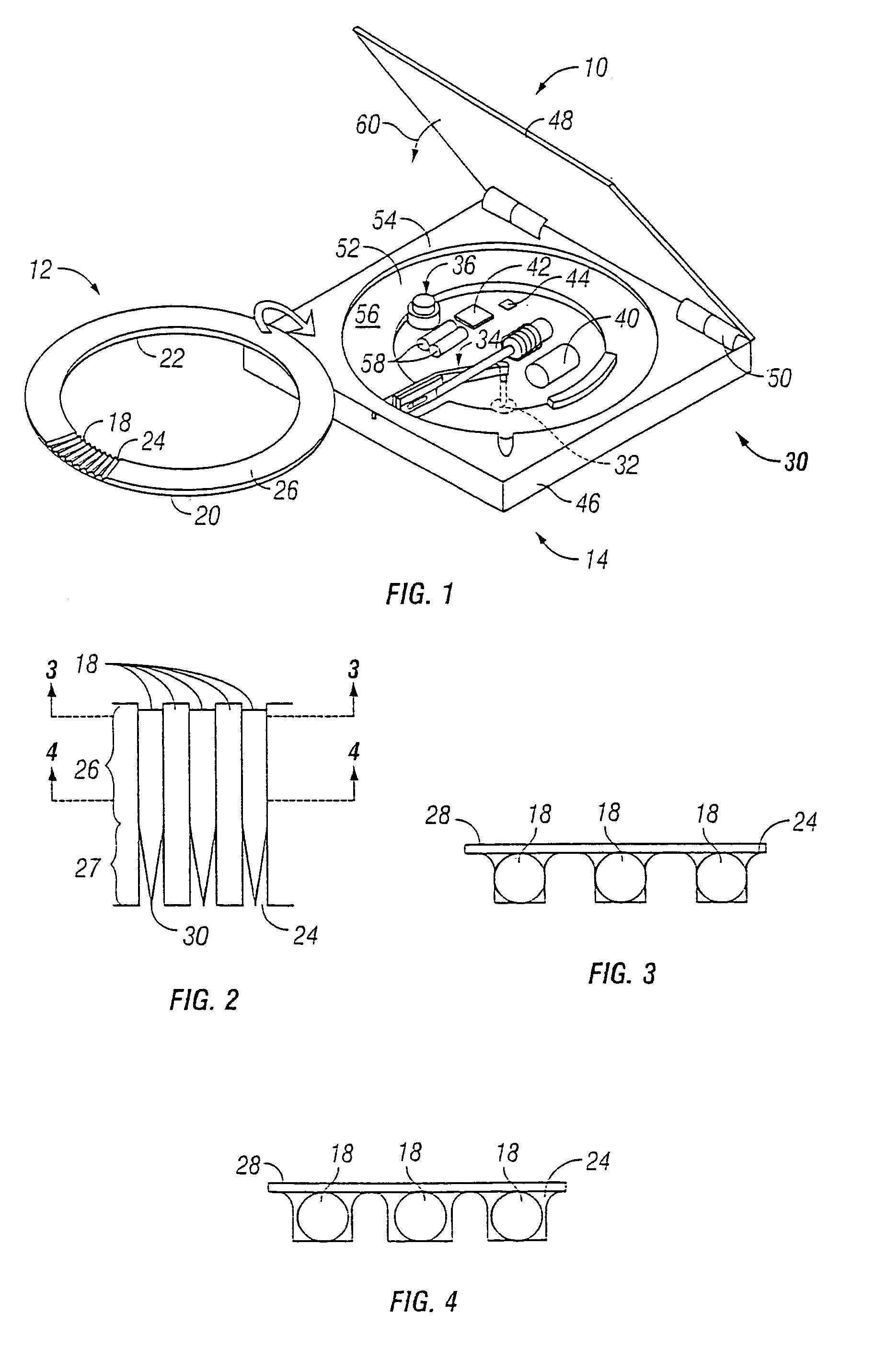
A body fluid sampling device for extracting bodily fluid from an anatomical feature is provided. The device comprises a penetrating member driver for driving a penetrating member to create a wound to extract bodily fluid; a light source positioned to indicate a point of sampling where the wound will be created, the light source indicating the point of sampling with a beam of light. The light source may be selected from one of the following: an LED, incandescent, fluorescent, or electroluminescent light source.

Description

RELATED APPLICATIONS[0001]This application is a continuation-in-part, and claims priority under 35 USC §120 to commonly assigned, copending U.S. patent application Ser. No. 10 / 323,622 filed on Dec. 18, 2002, which is a continuation-in-part of commonly assigned, copending U.S. patent application Ser. No. 10 / 127,395 filed Apr. 19, 2002. This application is also a continuation-in-part, and claims priority under 35 USC §120 to commonly assigned, copending U.S. patent application Ser. No. 10 / 237,261 filed Sep. 5, 2002. This application is further a continuation-in-part, and claims priority under 35 USC §120 to commonly assigned, copending U.S. patent application Ser. No. 10 / 420,535 filed Apr. 21, 2003. The present application also claims the benefit of priority under 35 USC § 119(e) to commonly assigned, copending U.S. Provisional Patent Application Ser. No. 60 / 393,706 filed Jul. 1, 2002; commonly assigned, copending U.S. Provisional Patent Application Ser. No. 60 / 393,707 filed Jul. 1, 2...

Claims


Application Information

Patent Timeline
IPC IPC(8): A61B5/00A61B5/15A61B5/155
CPCA61B5/1411A61B5/1427A61B5/14532A61B5/1455A61B5/15146A61B5/157A61B5/14551A61B5/150022A61B5/150152A61B5/150167A61B5/150175A61B5/150213A61B5/150305A61B5/150358A61B5/150412A61B5/150755A61B5/150824A61B5/15113A61B5/15123A61B5/15151A61B5/15161A61B5/15169A61B5/15171A61B5/15176A61B5/15182A61B17/8863Y10S436/808
Inventor BRIGGS, BARRY DEANFREEMAN, DOMINIQUE M.
Owner SANOFI AVENTIS DEUT GMBH
Learn More