Entry sheet for drilling

Active Publication Date: 2020-06-02
MITSUBISHI GAS CHEM CO INC
View PDF129 Cites 0 Cited by
  • Summary
  • Abstract
  • Description
  • Claims
  • Application Information

AI Technical Summary

Benefits of technology

[0012]In processing by use of a conventional entry sheet for drilling, the heat of friction between a drill bit and a laminate or a multilayer board melts a resin composition including a water-soluble resin and the like around the drill bit to thereby allow lubricity to be exhibited. As a side effect thereof, however, the resin composition is molten or thermally deformed to thereby cause the drill bit to be easily side slipped. Specifically, the tip of the drill bit proceeds into a layer including the resin composition and searches a biting point while being side slipped, and if the resin composition around the drill bit is here soft, a centripetal force acting on the drill bit becomes weak to cause side slipping of the drill bit to be hardly stopped. Therefore, in processing by use of a conventional entry sheet for drilling processing, there is a limit to enhancement in hole position accuracy. Herein, the “centripetal force” means an external stress that enhances centrality of the drill bit, and examples of the centripetal force include a stress that acts against the rotation center in rotation of the drill bit.
[0013]In view of such circumstances, an object of the present invention is to provide an entry sheet for drilling which is excellent in hole position accuracy and enables to reduce drill bit breakage as compared with a conventional entry sheet for drilling.
[0014]The present inventors have made various studies in order to so

Problems solved by technology

As a side effect thereof, however, the resin composition is molten or thermally deformed to thereby cause the drill bit to be easily side slipped.
Therefore, in processing by use of a conventional entry sheet for drilling processing, there is a limit to enh

Method used


Image

  • Entry sheet for drilling
  • Entry sheet for drilling
  • Entry sheet for drilling

Examples


example 1

[0098]Thirty parts by mass of polyethylene oxide having a weight average molecular weight of 150,000 (produced by Meisei Chemical Works Ltd., trade name: Altop MG-150) and 70 parts by mass of polyethylene glycol having a weight average molecular weight of 20,000 (produced by Sanyo Chemical Industries, Ltd., trade name: PEG20000) were dissolved in a mixed solution of water / MeOH (methanol) so that the resin concentration was 30% by mass, to provide a water-soluble resin solution. The ratio of water to MeOH was here a mass ratio of 60 / 40. Furthermore, 10 parts by mass of tungsten disulfide (produced by Japanese Lubricant Ltd., average particle diameter: 2 μm, purity: 98%) was added as a solid lubricant to the water-soluble resin solution based on 100 parts by mass of the resin in the water-soluble resin solution, and sufficiently dispersed to provide a resin composition solution. With the resin composition solution was coated a surface of an aluminum foil (item number of aluminum foil ...

examples 2 to 24

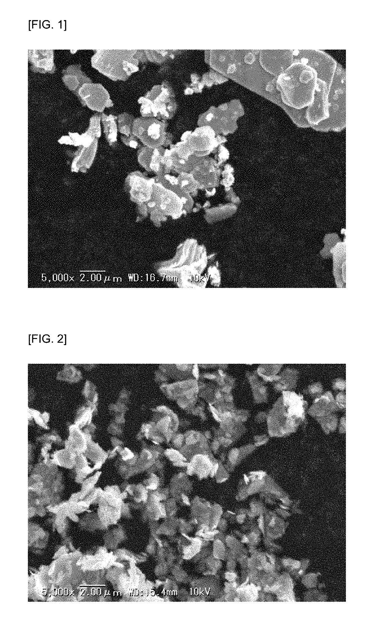
[0099]A resin composition solution was prepared according to Example 1 by use of the kind of each material at each rate shown in Table 4, and an entry sheet for drilling, in which the thickness of a resin composition layer after drying was 0.05 mm, was produced. Herein, a scanning electron micrograph (magnification: 5000×) of a part of the molybdenum disulfide used in Examples is illustrated in FIG. 2.


PUM


Abstract

The present invention provides an entry sheet for drilling which provides higher hole position accuracy than that of a conventional entry sheet for drilling. The present invention provides an entry sheet for drilling, including a metal foil, and a layer including a resin composition and formed on at least one surface of the metal foil, wherein the resin composition includes a resin and tungsten disulfide as a solid lubricant, and the content of the tungsten disulfide included in the resin composition is 10 parts by mass to 200 parts by mass based on 100 parts by mass of the resin included in the resin composition.

Description

CROSS-REFERENCE TO RELATED APPLICATIONS[0001]This application is a U.S. national phase application filed under 35 U.S.C. § 371 of International Application PCT / JP2015 / 059950, filed on Mar. 30, 2015, designating the United States, which claims priority from Japanese Application No. 2014-072337, filed Mar. 31, 2014, which are hereby incorporated herein by reference in their entirety.FILED OF THE INVENTION[0002]The present invention relates to an entry sheet for drilling.BACKGROUND OF THE INVENTION[0003]In a generally adopted method of drilling processing of a laminate or a multilayer board for use as a printed wiring board material, one laminate or multilayer board or a plurality of laminates or multilayer boards stacked are provided, and on the uppermost surface thereof, a sheet as an entry board is stacked which is a metal foil of aluminum or the like alone or includes such a metal foil and a resin composition layer formed thereon (hereinafter, such a sheet is usually referred to as...

Claims


Application Information

Patent Timeline
IPC IPC(8): H05K3/00B26F1/16B26D7/08
CPCB26D7/08H05K3/0047B26F1/16B26D7/088H05K2203/0214H05K2203/127B26F2210/02
Inventor MATSUYAMA, YOUSUKEOGASHIWA, TAKAAKI
Owner MITSUBISHI GAS CHEM CO INC
Why Eureka
Try Eureka